Apparatus and method for measuring a fluid flow rate profile using acoustic doppler effect

a technology of fluid flow rate and doppler effect, which is applied in the direction of liquid/fluent solid measurement, machines/engines, instruments, etc., can solve the problems of frequency dependence of the above-described flow velocity vsub>f /sub> and the flow rate q is left unsolved

Active Publication Date: 2008-04-22
FUJI ELECTRIC CO LTD
View PDF6 Cites 16 Cited by
  • Summary
  • Abstract
  • Description
  • Claims
  • Application Information

AI Technical Summary

Benefits of technology

[0016]Another aspect of the invention is a method of measuring the flow velocity profile as described above. The method includes mounting externally on the tubular member, the wedge, mounting the ultrasound transducer on the wedge as previously described, and setting the frequency of the transmitted ultrasonic wave emitted by the ultrasonic wave transducer at the frequency or the angle of incidence as described above.
[0065]Adequately setting of the transmitted frequency of an ultrasonic wave and the angle of incidence of the ultrasonic wave to the pipe enables realization of a clamp-on Doppler ultrasonic flow velocity profile meter can reduce the frequency dependence of a measured value due to Lamb wave, to reduce the measurement error. Moreover, the actual flow calibration of the ultrasonic wave transducer allows the offset error to be cancelled, allowing interchangeability between transducers to be ensured, by which a high accuracy can be maintained even when the combination with a converter is changed.

Problems solved by technology

However, the problem of frequency dependence of the above-described flow velocity Vf and the flow rate Q is left unsolved.

Method used


Image

  • Apparatus and method for measuring a fluid flow rate profile using acoustic doppler effect
  • Apparatus and method for measuring a fluid flow rate profile using acoustic doppler effect
  • Apparatus and method for measuring a fluid flow rate profile using acoustic doppler effect

Examples


Embodiment Construction

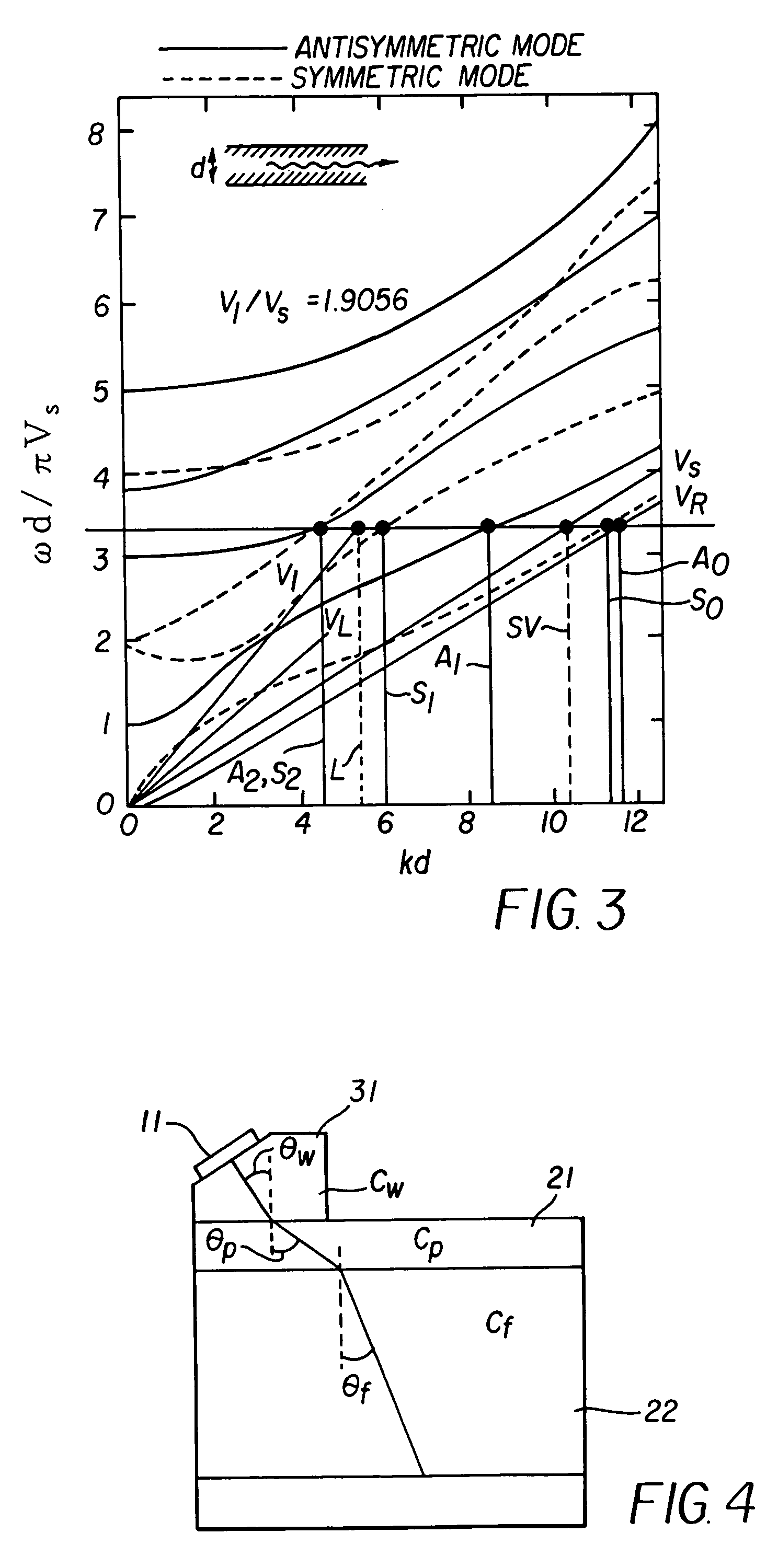
[0034]The preferred embodiments of the invention will be explained with reference to drawings. First, according to the studies carried out by the inventors, the above frequency dependence is caused by a dispersion phenomenon (a phenomenon of sound velocity variation depending on the frequency) occurring in a tubular member or body, e.g., a conduit or pipe. The dispersion phenomenon is, when the pipe is deemed to be a plate having the same wall thickness as that of the pipe, considered to be caused by normal modes of waves propagating in the plate with the plate taken as a waveguide. Here, each of the normal modes of waves in the plate is a sound wave having a specified frequency and a specified wavelength satisfying a boundary condition and propagating along an infinitely extending flat plate having a finite thickness. The occurrence of the normal modes of waves in the plate depends on the material and the thickness of the plate.

[0035]The normal modes of waves in the plate are prese...


PUM

PropertyMeasurementUnit
angle of incidenceaaaaaaaaaa
angleaaaaaaaaaa
flow velocityaaaaaaaaaa

Abstract

An apparatus and method for measuring a flow velocity profile of fluid traveling in a pipe or conduit uses an ultrasonic wave transmitted from an ultrasonic wave transducer mounted at an angle on the outside of a pipe using a wedge, and made incident onto the fluid in the pipe to measure the fluid flow velocity profile, using the principle that a frequency of an ultrasonic wave, reflected by a reflector existing in the fluid, is changed depending on a flow velocity due to Doppler effect. The transmission frequency and the angle of incidence onto the pipe can be selected to suppress frequency dependence of a measured value due to Lamb wave and allow the flow velocity or flow rate of fluid to be measured with a greater accuracy.

Description

BACKGROUND[0001]As is well-known, the clamp-on Doppler ultrasonic flow velocity profile meter measures a flow velocity profile or a flow rate of fluid by measuring the velocities of suspended particles or bubbles contained in the fluid, on the assumption that the suspended particles or bubbles move at the same velocity as that of the fluid. Referring to FIG. 14, which illustrates the operation principle of a Doppler ultrasonic flow velocity profile meter, an ultrasonic wave transducer 11 is secured and positioned to an outer surface of a pipe 21 at an angle relative to the pipe 21 with a sound wave propagative wedge 31. From the ultrasonic wave transducer 11, an ultrasonic wave pulse with a fundamental frequency of fO is transmitted to the pipe 21 at an angle of incidence θw. The incident ultrasonic wave pulse is reflected by reflectors 23, such as suspended particles, in a fluid 22 with a frequency of an echo shifted from the fundamental frequency, depending on the moving velocity ...

Claims


Application Information

Patent Timeline
Patent Type & Authority Patents(United States)
IPC IPC(8): G01F17/00G01F23/00G01L7/00G01F1/66G01P5/24
CPCG01F1/663G01F1/668G01F25/0007G01P5/241G01F25/10
Inventor KISHIRO, MASAMIYAMAMOTO, TOSHIHIROYAO, HIRONOBUOHMURO, YOSHINORIHIRAYAMA, NORITOMO
Owner FUJI ELECTRIC CO LTD
Why Eureka
Try Eureka