
Hand guard assembly for firearms

a technology for hand guards and firearms, applied in the field of accessories for firearms, can solve the problems of reducing the weight of hand guards and accessory mounting devices, adversely affecting the accuracy of firearms, and causing hand burns for operators, and achieve the effect of reducing weight and thermal mass

Active Publication Date: 2008-04-29
PATRIOT ORDNANCE FACTORY INC
View PDF10 Cites 100 Cited by
  • Summary
  • Abstract
  • Description
  • Claims
  • Application Information

AI Technical Summary

Benefits of technology

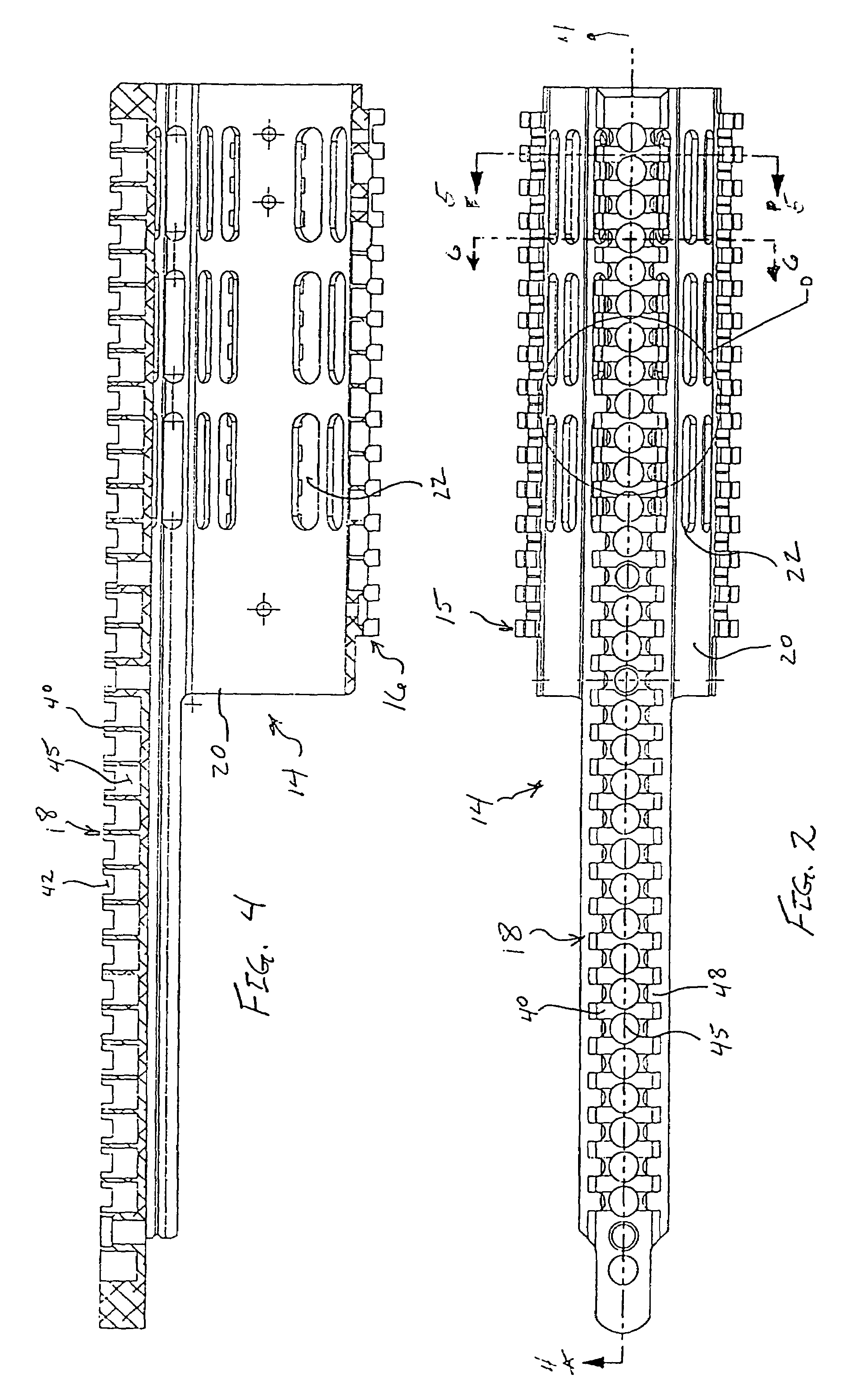
[0014]In a preferred method of fabricating the assembly, the body and any included accessory rails are extruded as a unitary structure. Also, portions of material are removed from the accessory rails to define the air flow openings as well as opposed longitudinally extending side grooves, the side grooves defining external reference surfaces for mounting accessories, a longitudinally extending central groove formed midway between the opposed side grooves and defining internal reference surfaces for mounting accessories, a plurality of transverse ribs with adjacent ribs being separated by crosscuts, and a plurality of pocket cuts formed intermediate the transverse ribs and along the central groove. The removal of the material also substantially reduces the weight and thermal mass.

Problems solved by technology

Further, many firearms are operated as automatic or semiautomatic and have a tendency to heat extensively so that handgrips attached directly to the barrel can produce hand burns for the operator if great care is not taken.
In addition, anything attached directly to the barrel of a firearm can have a tendency to alter the barrel slightly and any alterations can adversely affect the accuracy of the firearm.
One of the main problems that arises is the weight that hand guards and accessory mounting devices add to the firearm.

Method used


Image

  • Hand guard assembly for firearms
  • Hand guard assembly for firearms
  • Hand guard assembly for firearms

Examples


Embodiment Construction

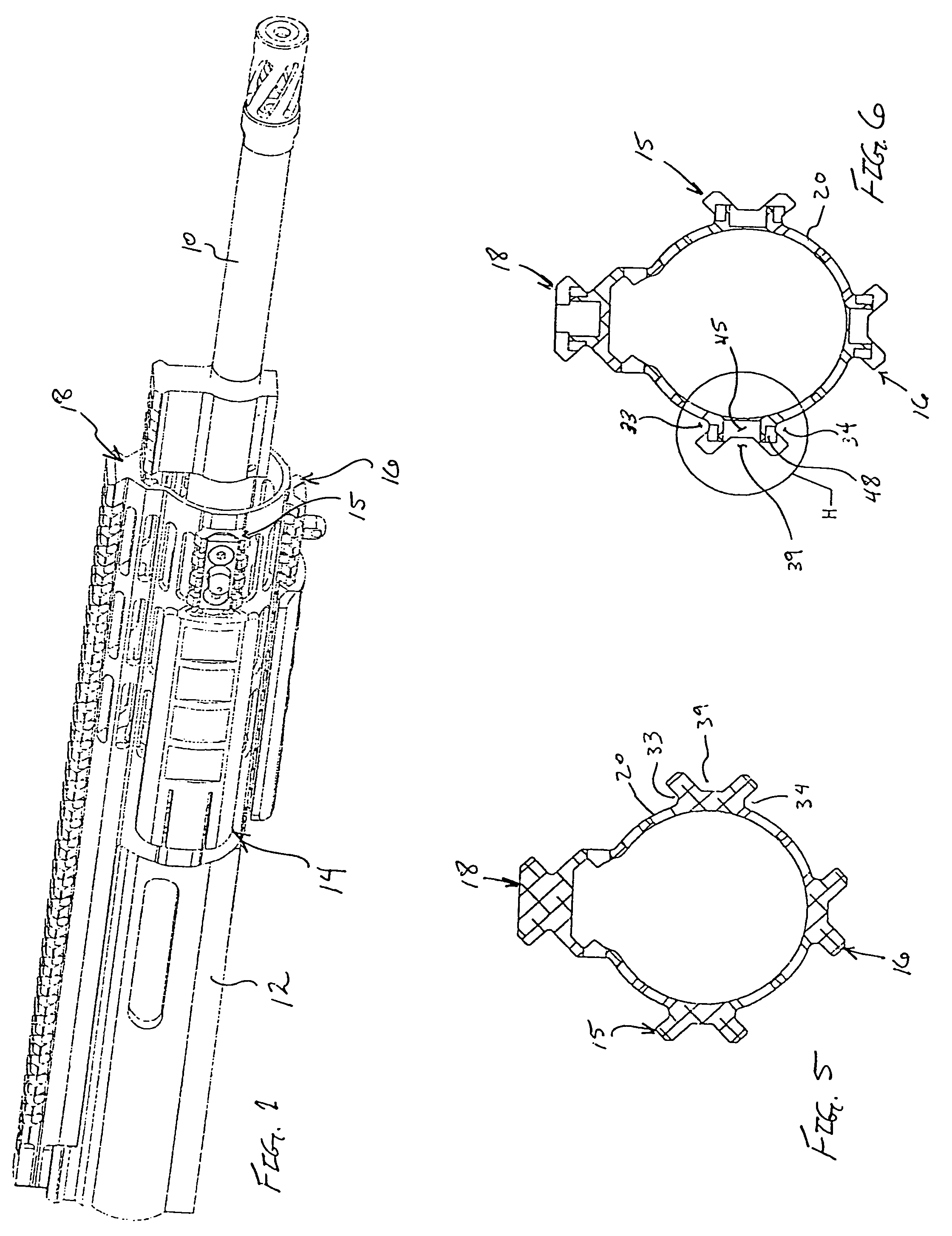
[0029]Turning now to the drawings in which like reference characters indicate corresponding elements throughout the several views, attention is directed to FIG. 1 which illustrates a portion of a firearm having a barrel 10 extending from an upper receiver 12. A hand guard 14, including side accessory rails 15, bottom accessory rail 16 and top rail 18, is carried by the portion of the firearm illustrated. Hand guard 14 is preferably extruded as a single piece having each element integrally formed therewith. This unitary construction adds strength while allowing removal of material, as will be described presently, to reduce weight and thermal mass. While hand guard 14 is illustrated mounted on a rifle, it will be understood that it may be mounted on substantially any firearm. Additionally, while side accessory rails 15, bottom accessory rail 16 and top rail 18 are illustrated carried by hand guard 14, some or all may be omitted as desired or included in conjunction with other firearms...


PUM


Abstract

A hand guard assembly for a firearm including a barrel. The assembly includes a tubular unitary body mounted to surround a portion of the barrel substantially coaxially and in a transversely spaced relationship. The tubular body includes a plurality of air flow openings formed therethrough and at least one of a top rail formed as a unitary portion of the tubular body and extending rearwardly along an upper portion of a receiver of the firearm, side accessory rails formed as a unitary portion of the tubular body and on opposed sides of the tubular body, and a bottom accessory rail formed as a unitary portion of the tubular body and on a bottom surface of the tubular body. In the preferred method of fabricating the assembly, the body and any include accessory rails are extruded.

Description

CROSS-REFERENCE TO RELATED APPLICATIONS[0001]This application claims the benefit of U.S. Provisional Application No. 60 / 585,746, filed 6 Jul. 2004FIELD OF THE INVENTION[0002]This invention relates to accessories for firearms.[0003]More particularly, the present invention relates to hand guards that may include one or more accessory rails.BACKGROUND OF THE INVENTION[0004]It is understood that hand-held firearms require some type of handgrip so that the operator can hold the firearm as it is fired. Also, many accessories are available that aid in the proper and / or enhanced operation of firearms and some type of platform or mounting structure is generally provided or available as an accessory for this function. Further, many firearms are operated as automatic or semiautomatic and have a tendency to heat extensively so that handgrips attached directly to the barrel can produce hand burns for the operator if great care is not taken. In addition, anything attached directly to the barrel o...

Claims


Application Information

Patent Timeline
Patent Type & Authority Patents(United States)
IPC IPC(8): F41G1/16
CPCF41C23/16F41G11/003
Inventor DESOMMA, FRANKDAVIES, ROBERT B.
Owner PATRIOT ORDNANCE FACTORY INC
Learn More