Motor, actuator and controller thereof

a technology of actuators and motors, applied in the direction of electric controllers, ignition automatic control, instruments, etc., can solve the problems of loss of torque, reduced motor efficiency, irregular torque, etc., and achieve stable and high-efficiency movement.

Inactive Publication Date: 2008-04-29
SONY CORP
View PDF21 Cites 7 Cited by
  • Summary
  • Abstract
  • Description
  • Claims
  • Application Information

AI Technical Summary

Benefits of technology

[0088]Furthermore, the present invention provides an excellent servo controller for an actuator, which can be employed as a joint actuator of a robot wherein each axis link is controlled with high-gain PD control.
[0089]Furthermore, the present invention provides an excellent servo controller for an actuator, wherein the compliance (mechanical compliance) can be adjusted, thereby providing stable and high-efficient movement.

Problems solved by technology

However, the aforementioned arrangement effects such performance by controlling the feed forward gain, and the aforementioned documents make no mention whatever of the viscosity of the joint, and frequency properties, and furthermore make no mention whatever of compliance of the joint.
The reason is that harmonic current occurring due to the permanent magnet loops at the time of the motor rotating at a high speed, leading to reduction of the efficiency of the motor).
At the time of the coil of the motor becoming open circuited, the current (more precisely, the flow of charges), which flows in the coil of the motor, decays, leading to loss of torque.
Furthermore, motors having such a configuration often cause irregularity in torque due to cogging.
That is to say, at the time of the coil of the motor becoming open circuited, the current (more precisely, the flow of charges), which flows in the coil of the motor, decays, leading to loss of torque.
Furthermore, the motor having such a configuration often causes irregularity in torque due to cogging.

Method used


Image

  • Motor, actuator and controller thereof
  • Motor, actuator and controller thereof
  • Motor, actuator and controller thereof

Examples


Embodiment Construction

[0130]Description will be made below in detail regarding embodiments according to the present invention with reference to the drawings.

A. Configuration of Actuator Motor

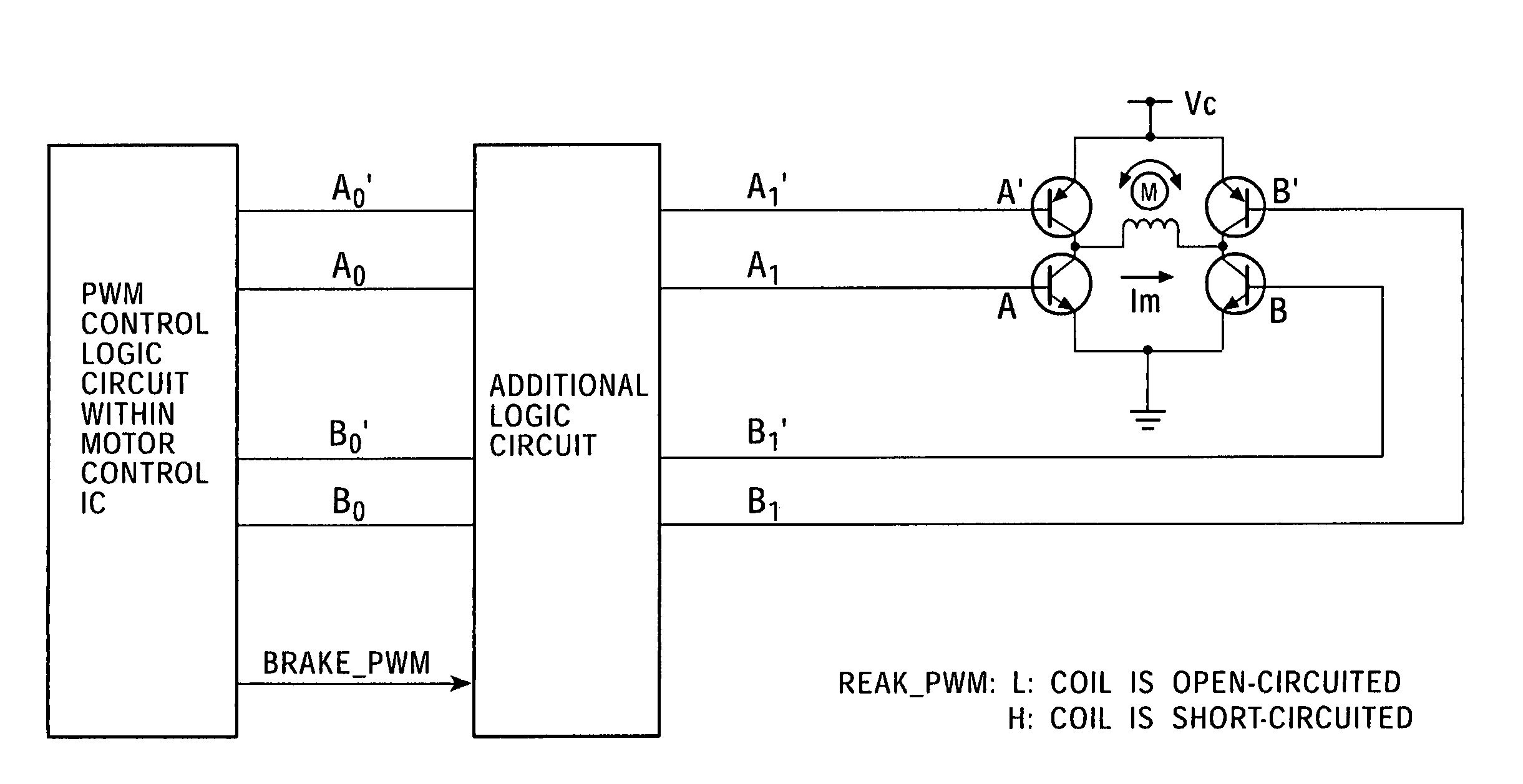
[0131]In general, a motor having a configuration wherein current supplied to the coil is controlled so as to form a predetermined magnetic flux distribution, thereby generating rotational torque, comprises a switching circuit formed of a first transistor switch set for connecting the terminals of coils to the power supply voltage, and a second transistor switch set for grounding the terminals of the coils, wherein the switching circuit is driven under the PWM control so as to control coil currents, thereby obtaining a desired torque, rotational position, rotational speed, and the like.

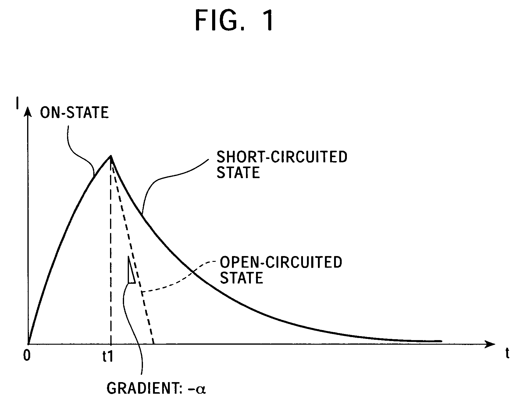
[0132]However, at the time of no current being applied to the coils of the motor due to the coils being open circuited, the current (more precisely, the flow of charges), which flows in the coil of the motor, decays, leading to loss of ...


PUM


Abstract

A motor comprises: coil on/off switching devices for switching between an on-state wherein current is supplied to the coils, and a first off-state wherein the coil terminals are open-circuited or a second off-state wherein the coil terminals are short-circuited; and a coil current control device for controlling switching operations of the coil on/off switching devices according to commands input to the motor. In the event that motor movement with great mechanical compliance is required, the ratio of the period of the first off-state is increased, and on the other hand, in the event that motor movement with great viscosity resistance is required, the ratio of the period of the second off-state is increased. This solves the problems of torque loss and cogging during a period wherein no current is applied to the coil.

Description

BACKGROUND OF THE INVENTION[0001]1. Field of the Invention[0002]The present invention relates to a motor and actuator controller, applied to a device or an apparatus employing a multi-axial driving system such as a robot, general-purpose assembly apparatus, robot-hand apparatus, or other multi-axial controllers, and particularly to an AC or DC motor or actuator controller which generates rotational torque due to formation of a predetermined magnetic distribution by controlling a supplied current to a coil thereof.[0003]More specifically, the present invention relates to a controller for an AC or DC motor or actuator wherein the coil current is controlled by PWM switching, and particularly to a controller which solves the problems of torque loss and cogging at times other than the on-period.[0004]Furthermore, the present invention relates to a servo controller for an actuator employed as a joint actuator for a robot wherein each axial link is controlled under high-gain PD control, an...

Claims


Application Information

Patent Timeline
Patent Type & Authority Patents(United States)
IPC IPC(8): B25J5/00H02P3/22H02P6/06H02P6/10H02P6/08H02P7/29H02P27/08
CPCH02P3/22H02P27/08
Inventor IRIBE, MASATSUGUYAMANAKA, HAJIMEITOH, YOSHIHIROSUZUKI, SHINYA
Owner SONY CORP
Why Eureka
Try Eureka