
A liquid piston compressor control system

A liquid piston and control system technology, applied in the field of compressors, can solve the problems of inability to maintain stability, increase in cylinder clearance, and reduce displacement, achieve stable gas-liquid two-phase interface, reduce clearance volume, and achieve effective control Effect

Active Publication Date: 2022-05-20
XI AN JIAOTONG UNIV
View PDF6 Cites 0 Cited by
  • Summary
  • Abstract
  • Description
  • Claims
  • Application Information

AI Technical Summary

Problems solved by technology

Due to the existence of liquid in the cylinder of the liquid piston compressor, without control, the high-speed movement will make it difficult for the liquid to keep up with the movement of the solid piston, and the follow-up between the liquid piston and the solid piston cannot be maintained
At this time, the gas-liquid two-phase interface will not be stable, and a part of the working medium gas is wrapped in liquid and difficult to discharge during the exhaust stage. As a result, with the operation of the compressor, the cylinder clearance continues to increase and the displacement decreases, which seriously affects the liquid piston. The working efficiency of the compressor

Method used


Image

  • A liquid piston compressor control system

Examples


Embodiment Construction

[0027] The present invention is described in further detail below in conjunction with accompanying drawing:

[0028] The present invention will be further described below in conjunction with embodiment. The following descriptions are only some, not all, embodiments of the present invention. Based on the embodiments of the present invention, all gas embodiments obtained by persons of ordinary skill in the art without creative efforts fall within the protection scope of the present invention.

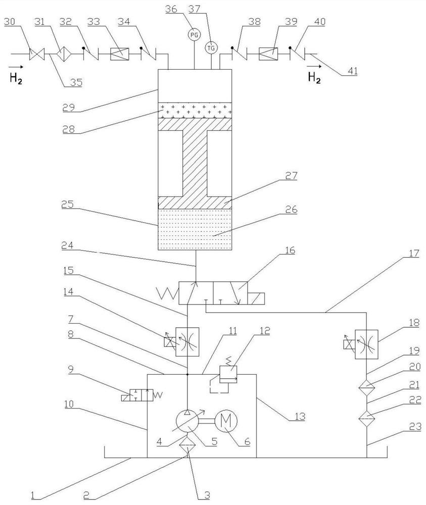
[0029] Such as figure 1 As shown, a liquid piston compressor control system, a gas compression assembly and a hydraulic assembly, the gas compression assembly and the hydraulic assembly are connected through pipelines;

[0030] The gas compressor assembly includes an intake pipeline, an exhaust pipeline, a gas compression chamber, and a hydraulic cylinder oil chamber;

[0031] The intake pipeline includes a solenoid valve 30, a gas filter 31, a first one-way valve 32, a first decompres...


PUM


Abstract

The invention discloses a control system of a liquid piston compressor. Electromagnetic valves are arranged on the intake pipeline and exhaust pipeline connected with the gas compression chamber of the liquid piston compressor, and the oil inlet of the first electromagnetic proportional speed regulating valve is respectively connected with the The oil outlet of the one-way variable hydraulic pump, the oil inlet of the two-position two-way electromagnetic reversing valve and the oil inlet of the relief valve are connected through pipelines, the oil outlet of the second electromagnetic proportional speed regulating valve, the two-position two-way The oil outlet of the electromagnetic reversing valve and the oil outlet of the overflow valve are both connected to the oil tank, and the oil inlet of the one-way variable hydraulic pump is connected to the oil through the oil pipe to form a pressure-stabilizing buffer structure, which changes the relationship between the liquid piston and the solid piston. The mode of action, during the movement of the piston from the top dead center to the bottom dead center, can effectively control and ensure the follow-up between the liquid piston and the gas piston, stabilize the gas-liquid two-phase interface, and reduce the surplus generated during the working process of the compressor. The gap volume realizes the efficient and stable operation of the compressor, and improves the adaptability of the liquid piston compressor to wide working conditions.

Description

technical field [0001] The application belongs to the technical field of compressors, and in particular relates to a liquid piston compressor control system. Background technique [0002] The development of the world today is facing the dual challenges of huge and environmental problems. Hydrogen energy, as a zero-emission, pollution-free, sustainable green energy, is considered to be an important way to solve energy problems in the new century. Among the many application fields of hydrogen, hydrogen fuel cell vehicles are expected to become the primary breakthrough and an important outlet for the hydrogen energy industry, and become the best technical route for new energy vehicles, as well as an important development strategy for my country's future automobile industry. Mature, stable, safe, reliable and efficient high-pressure hydrogen refueling station equipment is the premise and foundation for the development of the hydrogen fuel cell vehicle industry. [0003] Taking ...

Claims


Application Information

Patent Timeline
Patent Type & Authority Patents(China)
IPC IPC(8): F04B49/00F04B35/02
CPCF04B49/002F04B35/008Y02E60/32
Inventor 李云刘泽坤高秀峰康祥
Owner XI AN JIAOTONG UNIV
Learn More