
Arc fault identification using model reference estimation

a technology of model reference and fault identification, applied in the direction of digital computer details, instruments, nuclear elements, etc., can solve the problems of high current inrush, inability to adequately describe the load behavior, and difficulty in identifying faults, etc., and achieve the effect of robustness to nuisance tripping

Active Publication Date: 2008-04-29
X L SYNERGY
View PDF29 Cites 44 Cited by
  • Summary
  • Abstract
  • Description
  • Claims
  • Application Information

AI Technical Summary

Benefits of technology

[0020]U.S. Pat. Nos. 6,362,629 and 6,747,459 (Parker et al.) disclose a technique for arc detection by filtering a signal that is proportional to current and then comparing the frequency to a known arc signature spectrum. The use of fractal subsets is said to enhance arc detection reliability.
[0031]Prior art inventions are primarily directed at alternating current (AC) power distribution systems, and require faulting through multiple cycles before an arc is detected. Frequency domain based techniques require complicated discrete Fourier transform algorithms which are computationally complex. For many techniques, concerns about nuisance tripping requires rule exceptions and modifications that result in cumbersome algorithms that will be slow to respond for all but the most severe fault conditions. In contrast, the present invention has the following objects and advantages:

Problems solved by technology

However, if an electrical arcing fault occurs, this is complicated behavior that is not easy to describe and the model will not adequately describe the behavior of the load.
This causes high current inrush when the lamp is first turned on.
Dimmer circuits that operate by controlling the phase of a lamp use solid state switching elements and are highly nonlinear.
However, in steady state, the overall load characteristic of these devices is largely second order with frequency components that are multiples of the fundamental forcing function.

Method used


Image

  • Arc fault identification using model reference estimation
  • Arc fault identification using model reference estimation
  • Arc fault identification using model reference estimation

Examples


Embodiment Construction

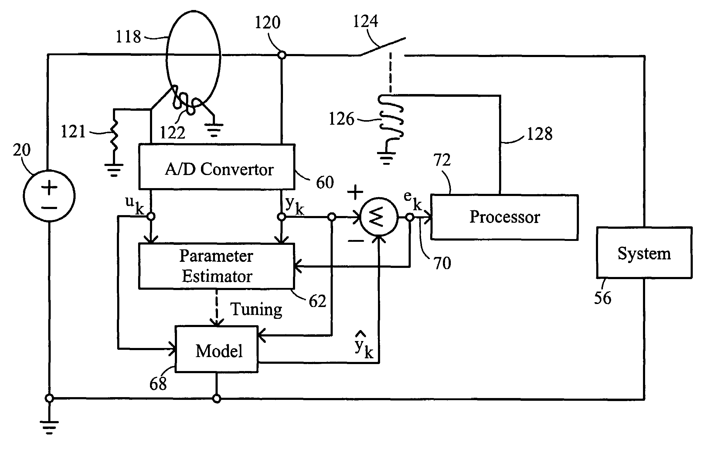
[0119]The present invention is for a method and apparatus for identifying electrical arcing faults in an electrical branch. When an arcing fault is identified, it may be interrupted, or in some cases, managed, so as to prevent extensive damage to electrical wiring.

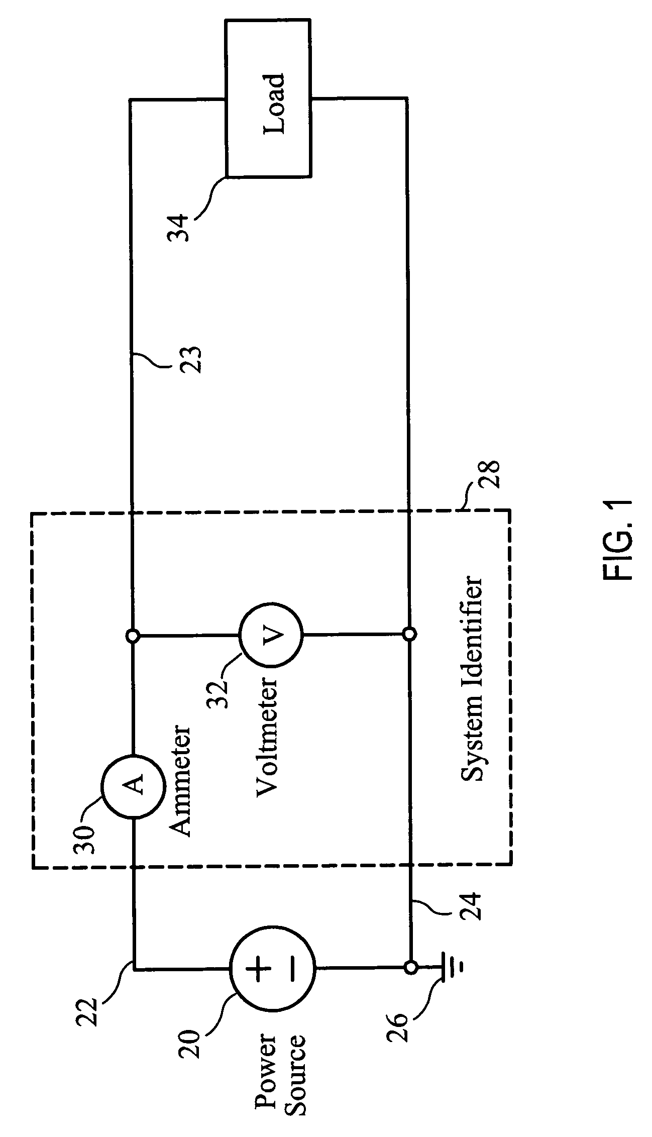
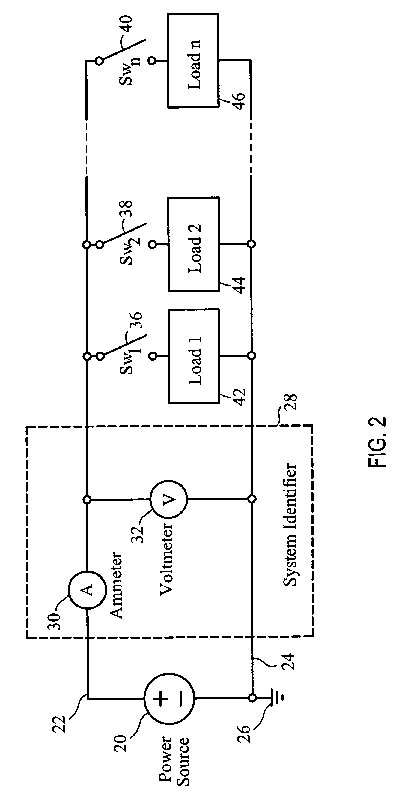
[0120]FIG. 1 depicts the elements needed for the identification of a load on an electrical branch. The electrical branch consists of a power source 20 which may be either direct current (such as a battery or DC power supply) or alternating current. The power source 20 connects to power delivery conductors 22 and 24. Power delivery conductor 24 is shown as connecting to an electrical ground 26 which serves as a point of reference for all voltage measurements. This electrical ground 26 may literally be attached to an earth ground, may be attached to the frame of an aircraft (in an aircraft application) or may simply be a reference point and not electrically attached outside of the circuit. For an alternating current power so...


PUM


Abstract

An apparatus and method for the identification of arcing phenomena in a faulted electrical network. By continually updating a model for the load on an electrical branch, an estimate of the behavior of that load may be calculated. Since electrical arcing faults result in a chaotic behavior that is difficult to describe, when arcing occurs, the model will be unable to adequately describe the arcing behavior and this inability indicates a fault condition, in response to which, power may be removed in full or in part from the faulted electrical network. In some embodiments, a current shunt is used to distinguish between source side and load side arcing. Some embodiments utilize a solid state switch as both current shunt and interruption means.

Description

STATEMENT REGARDING FEDERALLY SPONSORED RESEARCH OR DEVELOPMENT[0001]This invention was supported in part by the United States Air Force Research Laboratory under contract FA8650-04-C-2488.INCORPORATION BY REFERENCE OF MATERIAL SUBMITTED ON A COMPACT DISC[0002]Not Applicable.COPYRIGHTED MATERIAL[0003]Not Applicable.BACKGROUND OF THE INVENTIONField of the Invention (Technical Field)[0004]The present invention relates to an apparatus and method for quickly identifying an electrical arc fault condition in the wires of an electrical distribution system through the use of real time system identification coupled with model reference estimation.BRIEF SUMMARY OF THE INVENTION[0005]The present invention is of an apparatus and method for the rapid identification of arcing phenomena in a faulted electrical network. By continually updating a model for the load on an electrical branch, an estimate of the behavior of that load may be calculated. Since electrical arcing faults result in a chaotic ...

Claims


Application Information

Patent Timeline
Patent Type & Authority Patents(United States)
IPC IPC(8): G01R15/00G06F17/00
CPCG01R31/1272G01R31/088
Inventor NEMIR, DAVID C.BECK, JAN B.
Owner X L SYNERGY
Learn More