Split phase fuel conditioner

a fuel conditioner and split-phase technology, applied in the direction of engine ignition, high-pressure gas fuel injection, electric ignition installation, etc., can solve the problems of physical damage to the diesel engine, ignition delay persists, and all the accumulated fuel present along with that being injected tends to explode in an uncontrolled manner rather than steadily burn

Inactive Publication Date: 2008-05-06
BARRACK COMBUSTION PROCESS
View PDF7 Cites 17 Cited by
  • Summary
  • Abstract
  • Description
  • Claims
  • Application Information

AI Technical Summary

Benefits of technology

[0034]Preferably an inner circumferential surface of said sleeve is formed with one or more helical delivery grooves to assist in imparting a spiral motion to said second fuel volume injected into said transfer passage by said second injector.

Problems solved by technology

This often leads to the phenomenon of ignition delay which causes physical damage to the diesel engine as it forces peak cylinder pressure far higher than ordinarily desired.
While some progress has been made, ignition delay still persists.
While in theory this may seem straight forward, it is compromised by the very short time available during the conventional diesel cycle within which to vaporise the fuel.
As a consequence, instead of the injected fuel burning as soon as it is introduced into a main combustion chamber of the diesel engine, and thus liberate the heat value of the fuel at a controlled combustion rate, the ignition delay allows the fuel to accumulate such that upon finally reaching self-ignition temperature, all the accumulated fuel present along with that being injected tends to explode in an uncontrolled manner rather than steadily burn.
When close to TDC, due to the alignment of crank bearings, fast and sympathetic expansion of the combustion chamber is not possible.
Thus, in maintaining pressure and temperature equilibrium, a substantial proportion of the heat generated by the fuel is simply transferred to other engine components rather than being directed to useful work.
Further, the high peak pressure at TDC heavily loads the piston rings of the engine against its cylinder walls at a time when they are momentarily stationary (that is, changing from the upward compression stroke to the downward expansion stroke) and therefore unable to generate a hydrodynamic lubrication film.
This leads to unprotected metal-to-metal attrition further contributing to engine wear.

Method used


Image

  • Split phase fuel conditioner
  • Split phase fuel conditioner
  • Split phase fuel conditioner

Examples


Embodiment Construction

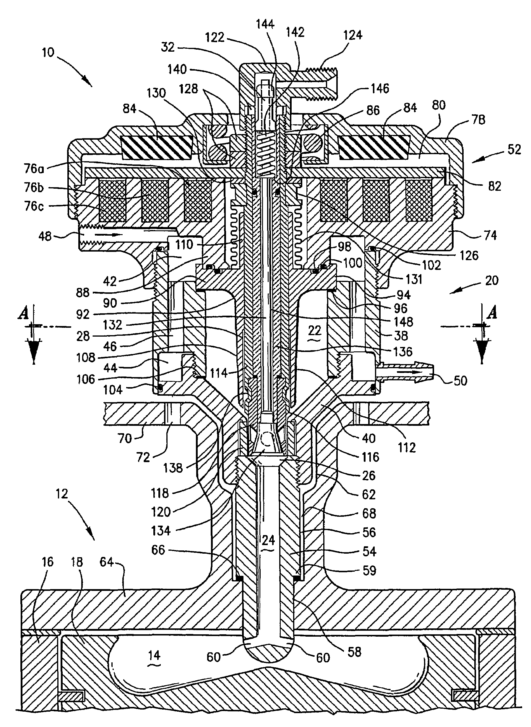
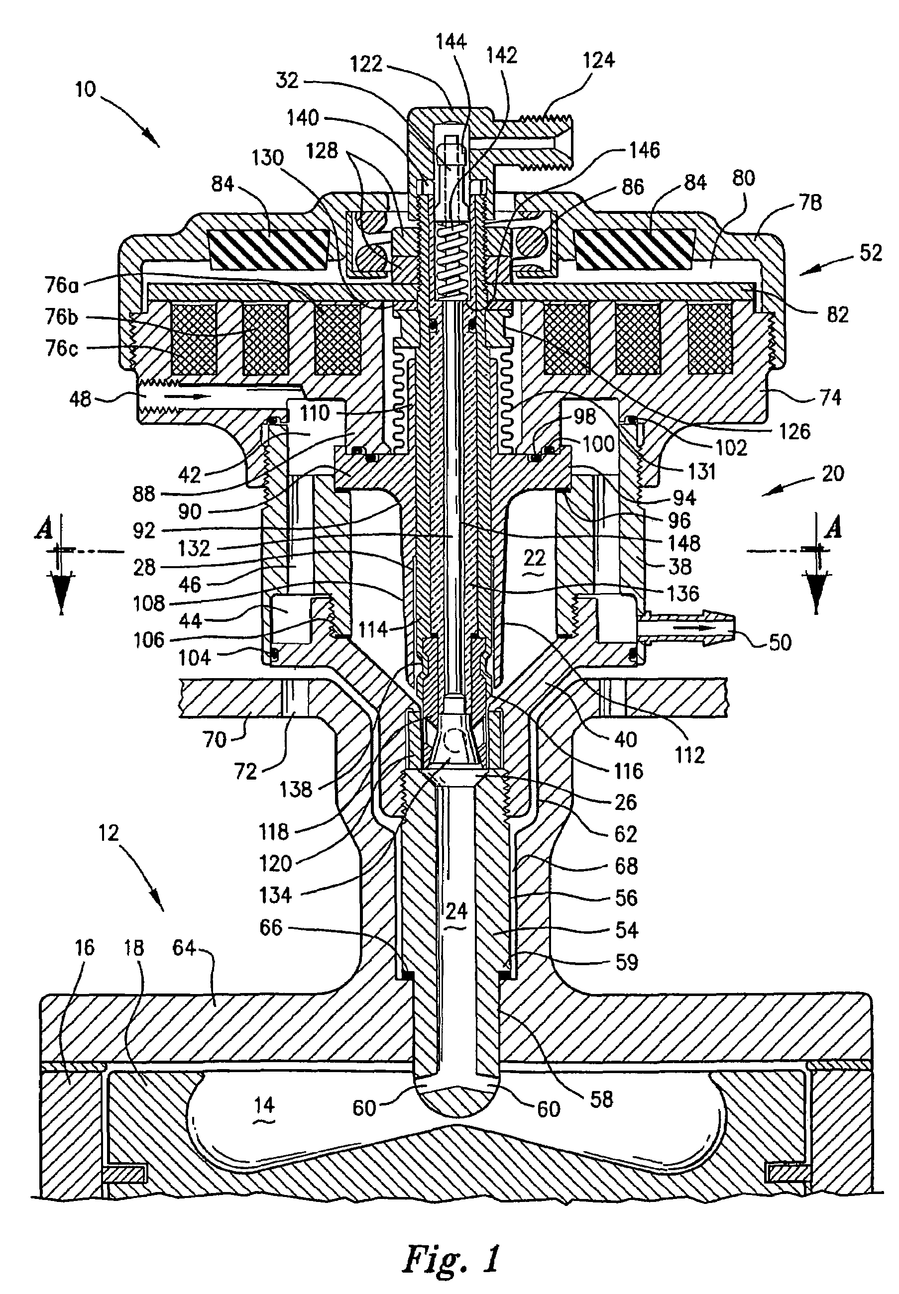
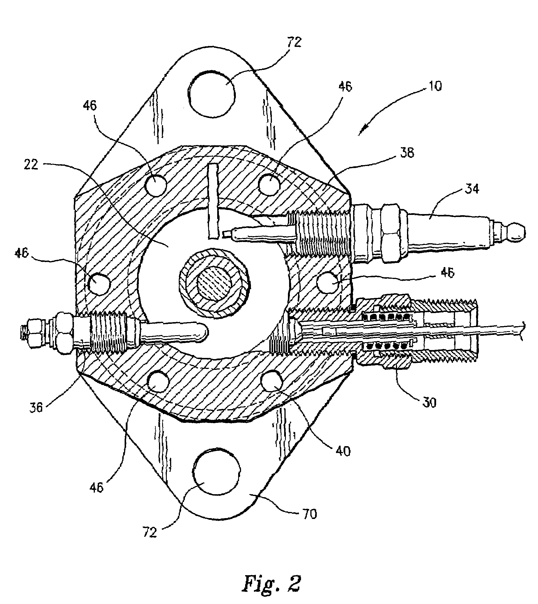
[0046]FIGS. 1 and 2 depict an embodiment of a split phase fuel conditioner 10 for an internal combustion engine 12 having a main combustion chamber 14 defined between an end of a cavity in the form of a cylinder 16 and a piston 18 housed within the cylinder 16. In the present embodiment where the engine 12 is a reciprocating piston engine 12, the engine 12 is likely to include a plurality of combustion chambers defined between respective cylinder ends and pistons. A separate split phase fuel conditioner is provided for each main combustion chamber. For simplicity, the following description is in relation to a single split phase fuel conditioner 10 associated with a single main combustion chamber.

[0047]The split phase fuel conditioner 10 includes a main body 20 defining an ignition chamber 22. A transfer passage 24 having first fluid communication means in the form of a throat 26 at one end for controlled fluid communication with the ignition chamber. The transfer passage 24 is also ...


PUM


Abstract

A split phase fuel conditioner 10 includes a main body 20 defining an ignition chamber 22. A transfer passage 24 is in fluid communication between the ignition chamber 22 and chamber 14. A valve 28 selectively opens and closes a throat 26 of the transfer passage 24 to control fluid communication between chamber 22 and chamber 14. A first injector 30 injects a first fuel volume into ignition chamber 22. A second fuel injector 32 injects a second volume of fuel directly into transfer passage 24 through the first valve 28. The first fuel volume is ignited in the chamber 22 to form an ignition plasma. Valve 28 is opened allowing the ignition plasma to condition the second fuel volume by vaporising the second fuel volume. The ignition plasma then sweeps the conditioned second fuel volume into the combustion chamber where it combusts in a controlled manner.

Description

[0001]This application is a PCT national stage entry of PCT / AU02 / 01586 filed Nov. 25, 2002, which claims Paris priority to Australian application PS2804, filed Jun. 7, 2002.FIELD OF THE INVENTION[0002]The present invention relates to a split phase fuel conditioner particularly, though not exclusively, for diesel engines, and engines operating on low grade and / or low octane rated fuels.BACKGROUND OF THE INVENTION[0003]An inherent characteristic of large bore direct injection diesel engines is the very short time available for the satisfactory introduction of fuel into the combustion chamber. This often leads to the phenomenon of ignition delay which causes physical damage to the diesel engine as it forces peak cylinder pressure far higher than ordinarily desired. Since the inception of diesel engines, substantial efforts have been placed in reducing the detrimental effects of ignition delay.[0004]Fuel technologists have attempted in part to decrease the phenomenon of ignition delay b...

Claims


Application Information

Patent Timeline
Patent Type & Authority Patents(United States)
IPC IPC(8): F02B19/02F02B19/12F02P13/00F02B19/14F02B19/16F02M43/04F02M61/04F02M61/08F02M61/14F02M63/00F02M67/04F02M67/08
CPCF02B19/02F02B19/12F02M43/04F02M61/042F02M61/08F02M67/04F02M67/08F02M63/0061F02M2200/306F02M2200/46Y02T10/125Y02T10/12
Inventor LAMPARD, ROBERT DOUGLAS
Owner BARRACK COMBUSTION PROCESS
Why Eureka
Try Eureka