Rodless modular conveyor belt

a modular, conveyor belt technology, applied in the direction of conveyors, transportation and packaging, etc., can solve the problems of connecting rods or pins contributing to the cost of the conveyor belt, subject to wear, etc., and achieve the effect of greater interconnection and greater tensile strength

Inactive Publication Date: 2008-05-06
HABASIT AG
View PDF10 Cites 10 Cited by
  • Summary
  • Abstract
  • Description
  • Claims
  • Application Information

AI Technical Summary

Benefits of technology

[0011]With the slotted embodiment just described, the pivot posts or dowels preferably are present on both sides of each knuckle or projection, and the counterpart knuckles have their slots on both sides, for greater interengagement and greater tensile strength.

Problems solved by technology

Connecting rods or pins contribute to the cost of the conveyor belt, are subject to wear, often unevenly along the pin, and must be retained in the belt against lateral movement and migration, as well as being removable when repair or replacement is needed.

Method used


Image

  • Rodless modular conveyor belt
  • Rodless modular conveyor belt
  • Rodless modular conveyor belt

Examples


first embodiment

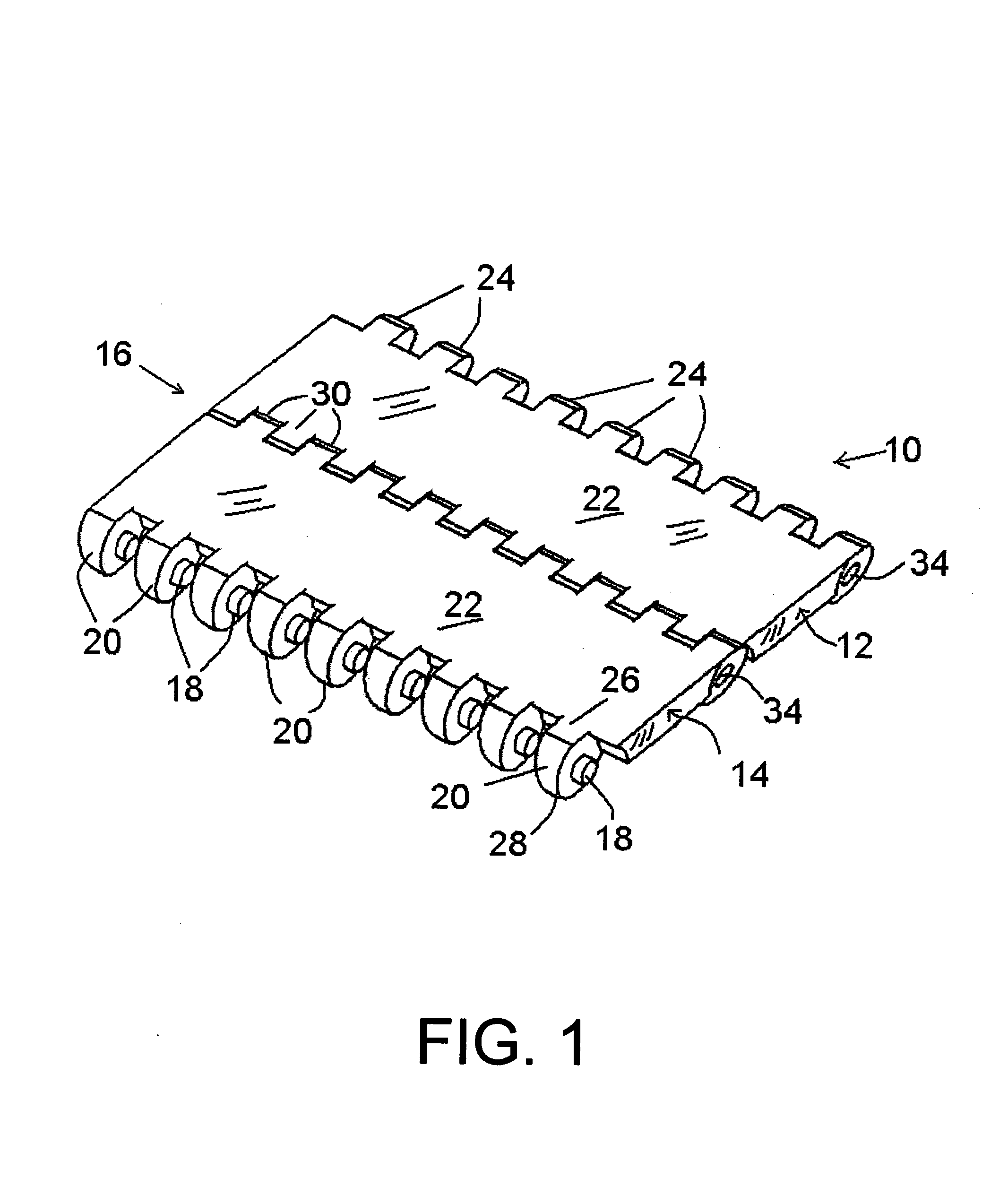
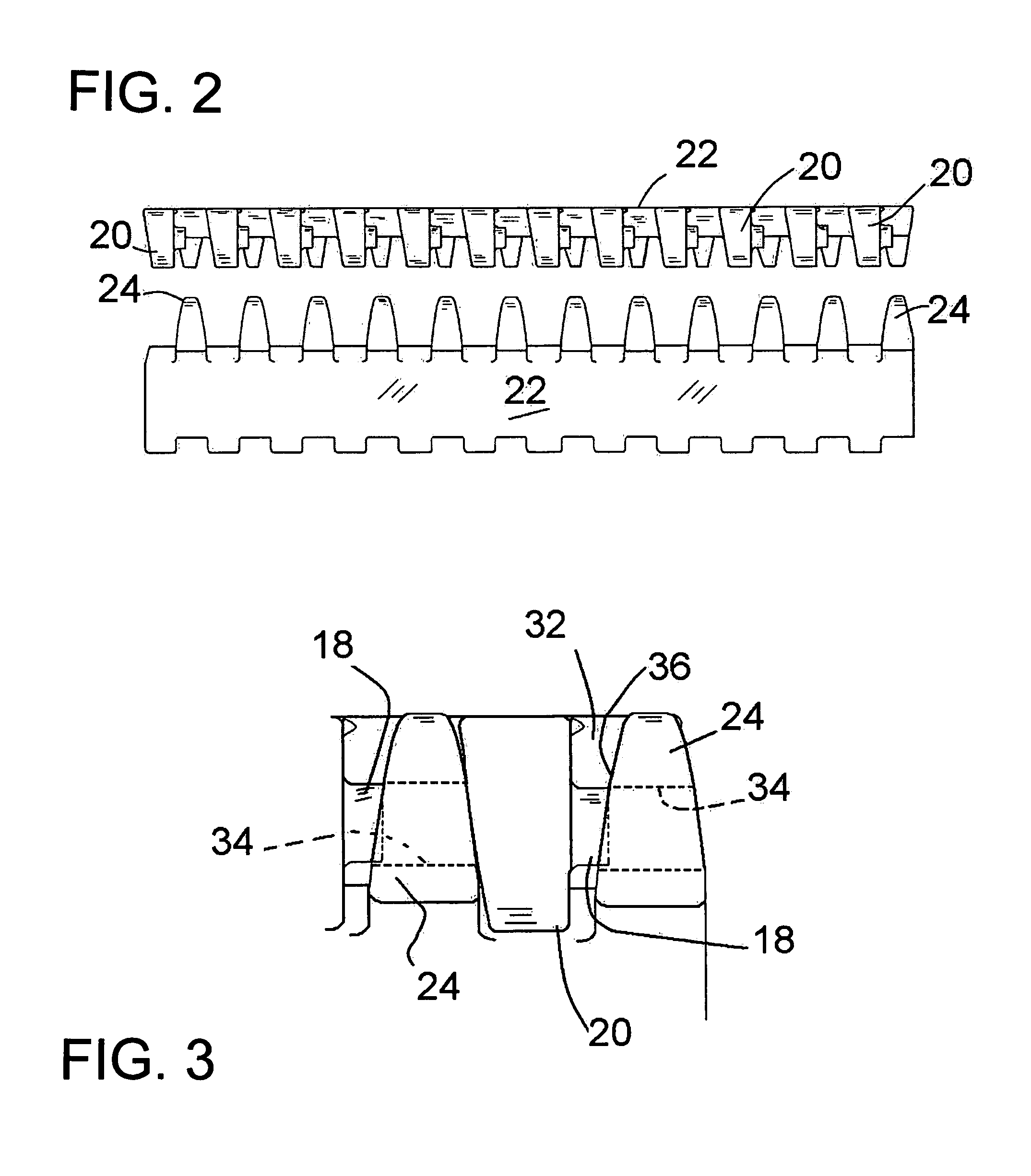
[0025]In the drawings, FIG. 1 shows in a first embodiment a portion of a belt 10 according to the invention, wherein adjacent modules 12 and 14, or module rows, are retained together along a hinge line 16 without connecting rods or pins. Connection between adjacent module rows is effected with pivot posts 18 which are integrally molded with the modules, extending laterally from projections or knuckles 20. These projections 20 extend as a set of essentially similar projections in one direction from a center section 22 of the module, and another group or set of projections 24 extend in the opposition direction, both along the line of the direction of travel. Herein and in the claims the term “first projections” is often applied to the projections 20, and the term “second projections” or “second set of projections” is often applied to the projections 24. However, this is not to imply any particular direction of travel; if there is a preferred direction of travel, either the projections...

second embodiment

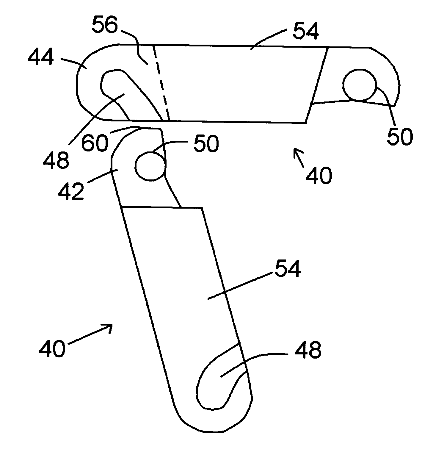
[0031]the rodless conveyor belt of the invention is shown in FIGS. 5 through 12. In this form of the invention the modules 40 have first and second groups of link ends or projections 42 and 44 that are not tapered. Again, this is preferably a solid top conveyor belt as shown, for straight travel. The belt portion 45 shown in FIGS. 5 and 6 is for illustration only, and the belt may be assembled in any desired length and a wide variety of widths, as in the above-described embodiment. In FIG. 6 module row ends, to be positioned at an edge of the belt, are shown on the modules 40. In a belt of single-module rows, these closing ends 46 will be present at each module end, but in the typical wider belt, the modules of adjacent rows will be interleaved or “brick-laid” such that joints between laterally adjacent modules are staggered rather than contiguous from row to row.

[0032]As seen in the drawings, the non-tapered link ends or projections 42 and 44 are assembled somewhat similarly to the...


PUM


Abstract

A conveyor belt assembled of modular plastic components is retained together without the usual connecting rods or pins. In one embodiment the modules, each of which has series of finger-like projections or knuckles both at forward and rear ends of the module, the projections are tapered to narrows in width from top to bottom. The projections at either the forward or rear side have laterally extending posts or dowels at one side of each projection, each with a length that extends through only part of the width of the gap between adjacent projections. In the opposite set of projections are holes, similar to the aligned holes that are present when module rows are connected by rods. With the projections being tapered, modules of adjacent rows can be put together by interdigiting the projections with the modules of adjacent rows held at an angle, preferably an acute angle beyond 90°. When the modules are brought back toward alignment to a common plane, the pivot posts of one module become locked in the holes of the module of the adjacent row.

Description

BACKGROUND OF THE INVENTION[0001]This invention concerns modular conveyor belts formed of integrally molded plastic modules interfitted together to form belts of any desired length and a broad range of different widths. The invention more particularly relates to elimination of pins or rods that normally extend through interdigited knuckles or projections of adjacent rows of modules to retain the rows together to form the belt.[0002]Conveyor belts of the general type with which this invention is concerned are shown in KVP U.S. Pat. Nos. 5,181,601, 5,645,160, and 5,706,934. In particular, one embodiment of the current invention relates to a configuration shown and described in U.S. Pat. No. 5,706,934.[0003]All of the above patents show modular plastic conveyor belts wherein rods or pins, sometimes very long, extend through apertures in the interdigited knuckles or projections of modules of adjacent rows, to hold the adjacent rows together while allowing pivoting motion between the mod...

Claims


Application Information

Patent Timeline
Patent Type & Authority Patents(United States)
IPC IPC(8): B65G17/06
CPCB65G17/08
Inventor HARRISON, JAMES J.
Owner HABASIT AG
Why Eureka
Try Eureka