Fiber optic cable protective apparatus

a protective device and fiber optic cable technology, applied in the field of fiber optic cable protective devices, can solve the problems of damaging the fiber, adversely affecting the ability of the fiber optic cable to transmit an optical signal without undue attenuation, and undesirable storage of the fiber optic cable in such a bag

Active Publication Date: 2008-05-06
FIBER OPTIC PROTECTION SYST
View PDF8 Cites 92 Cited by
  • Summary
  • Abstract
  • Description
  • Claims
  • Application Information

AI Technical Summary

Benefits of technology

[0010]Apparatus constructed in accordance with the invention comprises a casing formed of a rigid plastic material defining a protective hollow housing within which two separate spools are journaled for rotation conjointly or independently of one another. Around one spool is wound a selected length of a first fiber optic cable for controlled cable length extension from and retraction into the housing. A selected length of a second cable is wound about the second spool for controlled cable length extension from and retraction into the housing. The inner ends of the two cables confront one another and are supported in a 360° rotatable coupler on which the two spools are mounted for independent rotation through 360° in a selected one of two opposite directions. The inner ends of the two cables are maintained in axial alignment so that light energy may pass from one cable to the other without interruption or appreciable loss.
[0013]Each spool has an annular groove in which a selected length of cable is wound. Each groove communicates with a guide forming a path from the groove to the axis of rotation of the spools. The path formed by the guide avoids kinking, twisting, or otherwise damaging the fiber.

Problems solved by technology

The storage of a fiber optic cable in such a bag is undesirable because of the inability to maintain consistent control over minimum bending radii and the susceptibility to damage of such cable while accommodated in such bag.
Manual uncoiling of the cable frequently results in slack lengths of cable and the formation of unnecessary extra coils that may cause the cable to become twisted or kinked, whereas inconsistent control over manual recoiling of the cable subjects it to the possibility that it will be wound about a radius less than the minimum bending radius, thereby physically damaging the fiber and adversely affecting its ability to transmit an optical signal without undue attenuation.
In those instances in which the test set and a fiber optic jumper cable are shipped or stored in the same container, the fiber is exposed to the possibility of being damaged by the test equipment itself during transit.
The current practice, therefore, requires the selection of a length of cable which almost always is greater than the distance to be spanned, thereby resulting in excessive sagging and the formation of unnecessary extra coils distributed between the ends of the cable.
After use the recoiling of the cable by hand results in uncertain bending radii and increases the risk of damaging the fiber.
As a consequence the cable must be unwound from and rewound on the two spools in a predetermined order which may not always be convenient.

Method used


Image

  • Fiber optic cable protective apparatus
  • Fiber optic cable protective apparatus
  • Fiber optic cable protective apparatus

Examples


Embodiment Construction

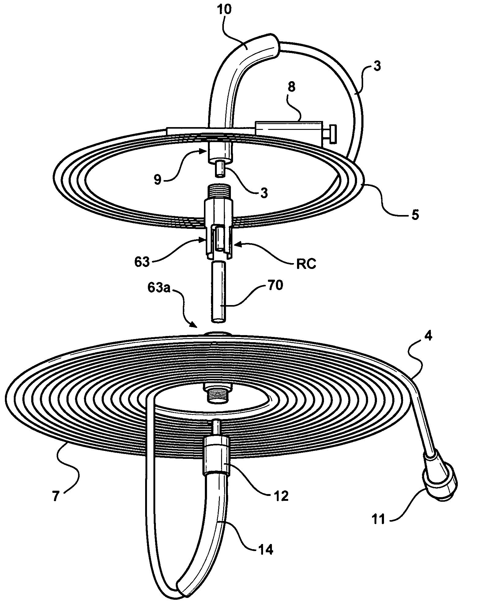
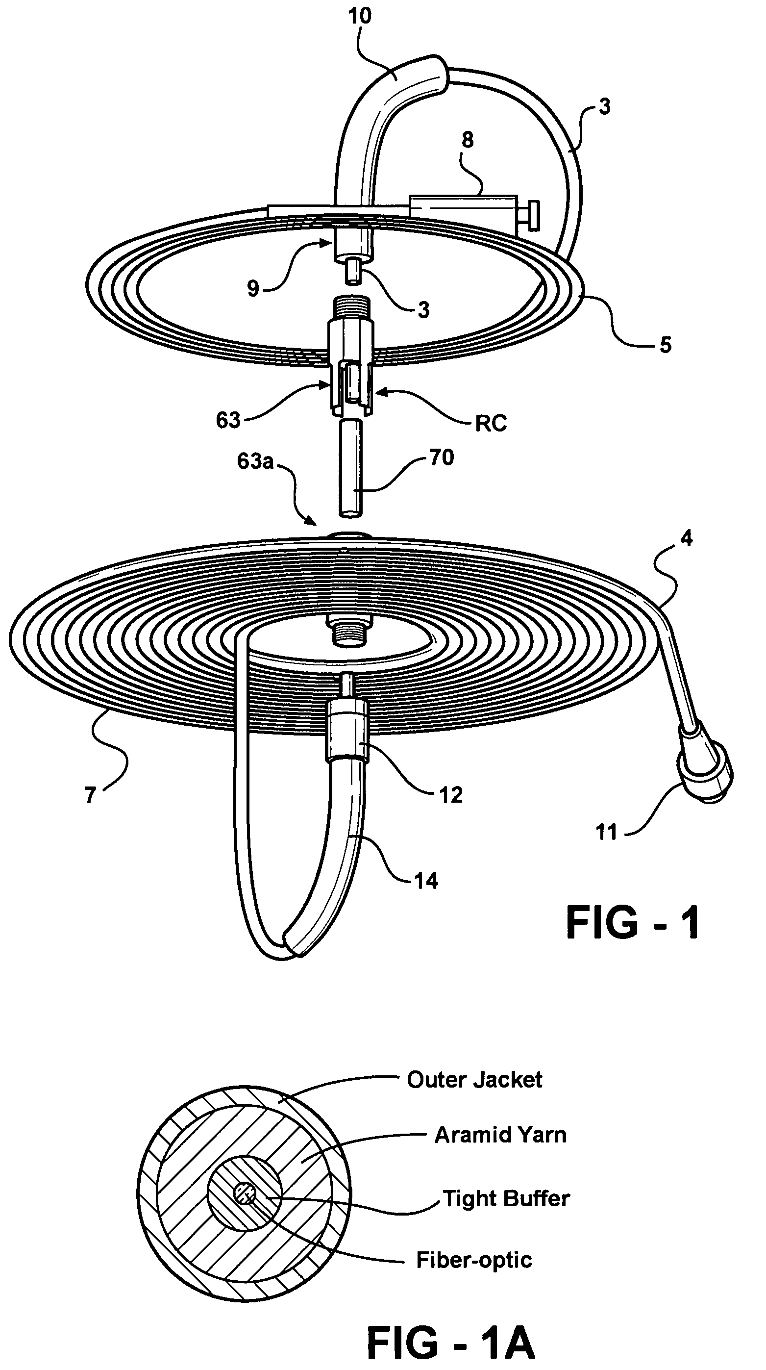
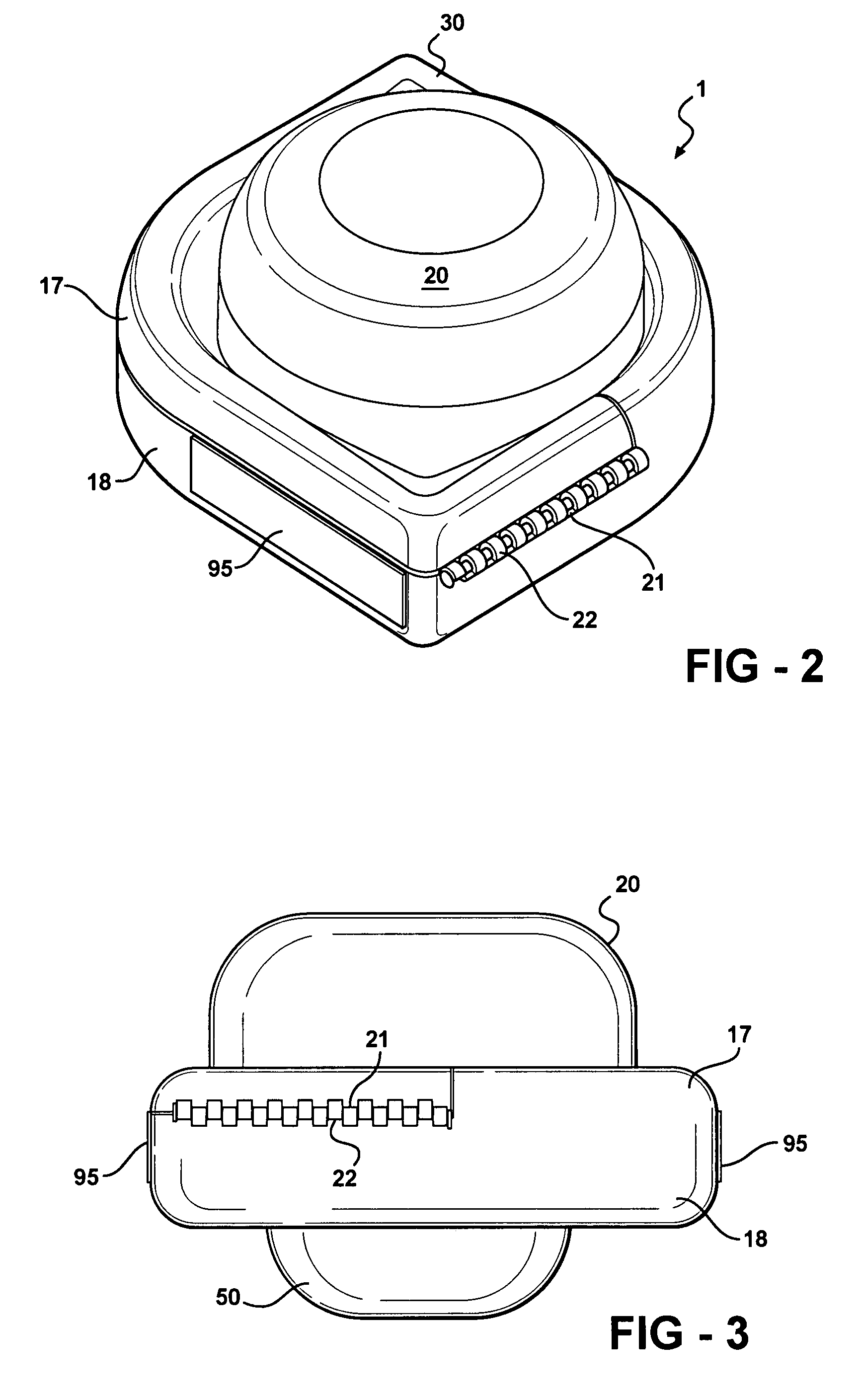
[0029]Apparatus constructed in accordance with the preferred embodiment of the invention comprises a casing 1 (FIGS. 2 and 3) formed from rigid plastic material, such as polycarbonate or that used in the manufacture of so-called jewel cases for compact discs and the like. The casing is adapted to contain, protect, and enable control to be exerted over two separate and independent lengths of coil able material, such as two conventional, fiber optic cables 3 and 4. As shown in FIG. 1 the cable 3 is a single simplex cable forming a first coil 5 and the cable 4 is a single simplex cable forming a second coil 7. The radius of each coil is at least as great as the minimum bending radius of the respective cables.

[0030]Each cable has, as is conventional, an axially and longitudinally extending glass core commonly referred to as a fiber which is capable of transmitting light energy the full length of the cable, the fiber being encircled by a tight buffer, aramid yarn, and an outer jacket for...


PUM


Abstract

A rigid casing provides support and protection for two separate fiber optic jumper cables of a fiber optic test set and which may be wound on two separate spools for extension and retraction relative to the casing. A selected length of one of the cables may be extended from the casing and connected to a part of a fiber optic circuit to be tested, following which a selected length of the other cable may be extended from the casing and connected to another part of the circuit. The spools are capable of rotation about a common axis with and relative to one another. The cables have confronting ends at the axis of rotation of the spools and in axial alignment so that light energy emitted from either cable may be received by the other without interruption.

Description

[0001]This invention relates to apparatus for storing coil able materials, such as a pair of separate fiber optic cables, wound about separate spools in a protective housing, the spools being rotatable through 360° independently of one another for extension and retraction of the respective cables from and into the casing in a consistent and controlled manner.BACKGROUND OF THE INVENTION[0002]When installing, testing, maintaining, or tuning all ranges of fiber optic networks it is necessary to make use of various test sets. A test set ordinarily will include one or more fiber optic jumper cables for verifying the integrity of the signal flow through various parts of a fiber optic circuit. A typical fiber optic jumper cable consist of two standard connectors, connected to a given length of a single simplex cable which is a standard cable manufactured by Dow Corning Corporation. For this application we are using a typical cable consisting of a glass fiber, surrounded by a teflon buffer ...

Claims


Application Information

Patent Timeline
Patent Type & Authority Patents(United States)
IPC IPC(8): G02B6/00
CPCB65H75/44G02B6/4457B65H2403/722B65H2701/32
Inventor KLINE, JAMES R.KLINE, THOMAS J.SENE, DUSTIN S.
Owner FIBER OPTIC PROTECTION SYST
Why Eureka
Try Eureka