
High-speed data readable information processing device

a data processing device and high-speed technology, applied in the field of data transfer control of information processing devices, can solve the problems of affecting the performance of the system as a whole, increasing the load on the cpu, etc., and achieve the effect of high-speed data reading

Active Publication Date: 2008-05-06
RENESAS ELECTRONICS CORP
View PDF9 Cites 0 Cited by
  • Summary
  • Abstract
  • Description
  • Claims
  • Application Information

AI Technical Summary

Benefits of technology

The present invention provides an information processing device that uses DMA transfer to ensure reliability of received messages from a CAN module and enables high-speed data reading. The device includes a message box for receiving and temporarily storing messages, a memory access control circuit, and a low-speed bus for transmitting messages. The message box outputs a message reception request when receiving a message, and the memory access control circuit accesses the message box and the main storage memory to transfer the message received in response to the message reception request and stored in the message box to the main storage memory. This prevents overwriting of messages stored in the message box and ensures message reliability.

Problems solved by technology

In such a case, the central processing unit (CPU) should constantly monitor the I / O apparatus under its control to wait for the completion of the data transfer operation, so that load on the CPU might be increased to degrade performance of the system as a whole.

Method used


Image

  • High-speed data readable information processing device
  • High-speed data readable information processing device
  • High-speed data readable information processing device

Examples


first embodiment

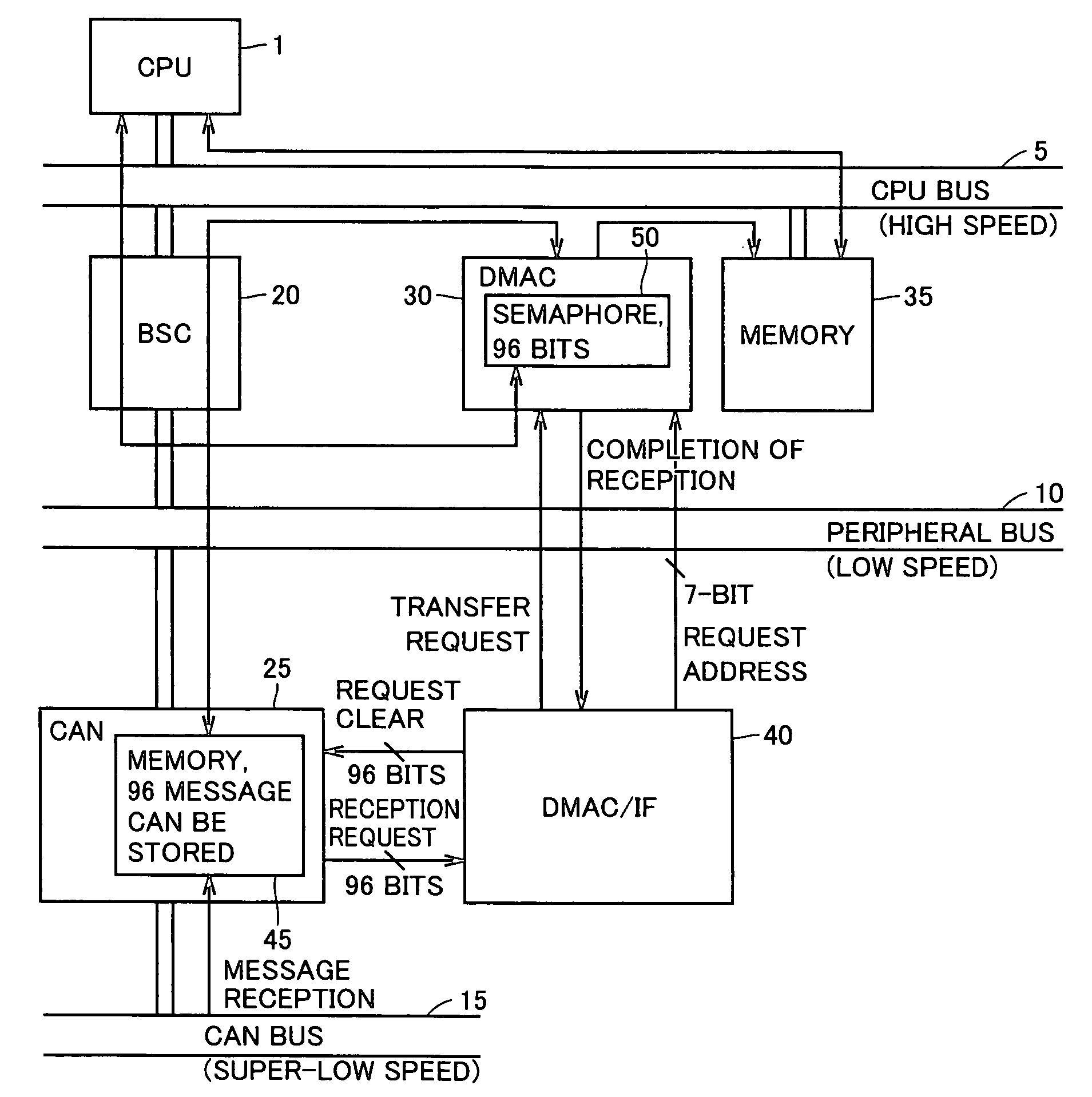
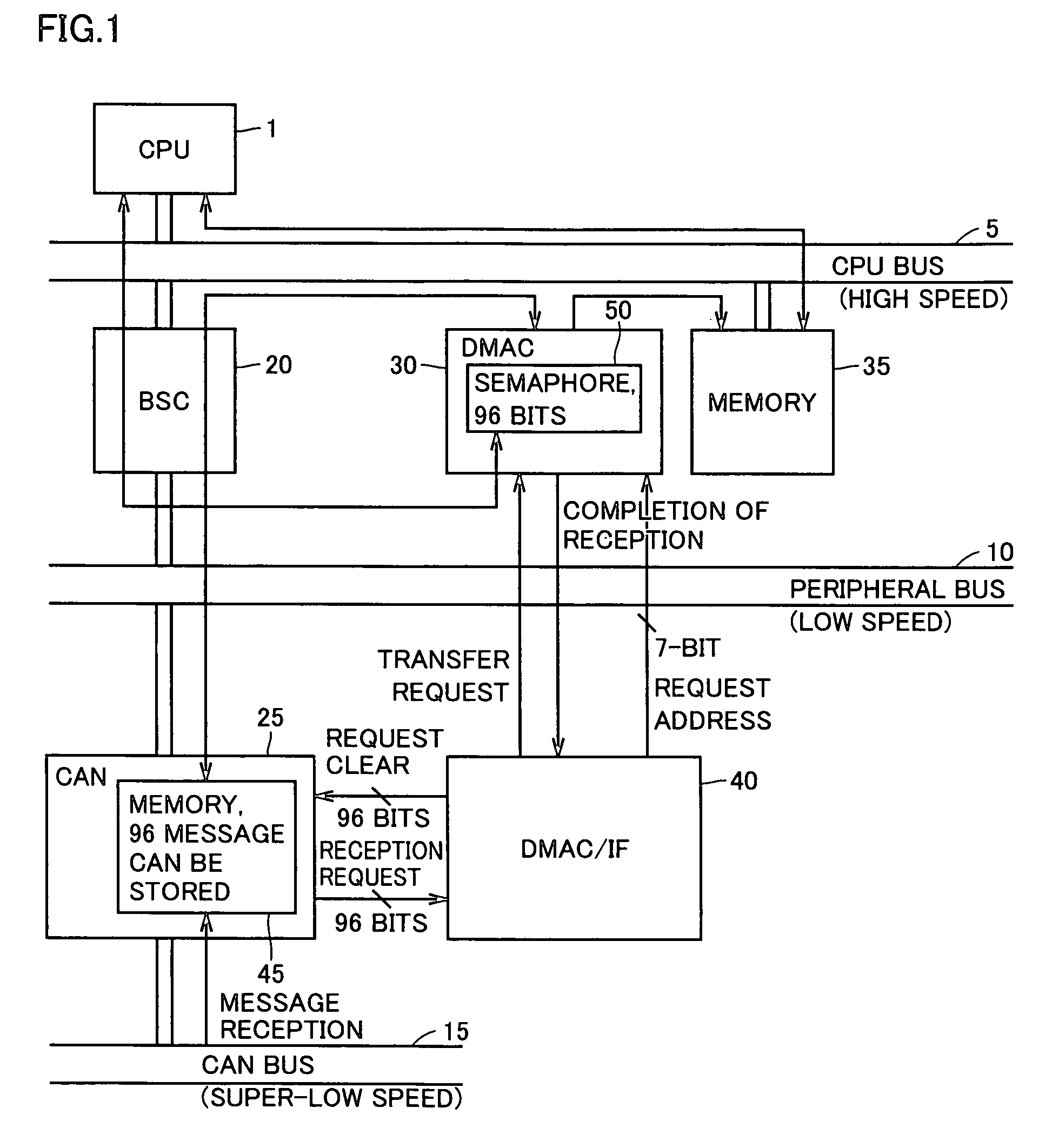
[0023]With reference to FIG. 1, an information processing device according to a first embodiment of the present invention includes a central processing unit 1, a memory 35 as a main storage device, a CPU bus 5 as a high-speed bus for connecting the central processing unit 1 and the memory 35, a DMAC unit 30 connected to CPU bus 5 for executing DMA transfer, a peripheral bus 10 for use in low-speed data transfer with an external apparatus and the like, a bus controller (BSC) 20 for controlling connection between peripheral bus 10 and CPU bus 5, a CAN bus 15 on which message information is transmitted at an extremely low speed, and a CAN module 25 which is connected to CPU bus 5 through peripheral bus 10 and receives and stores message information from CAN bus 15. Further included is a DMAC interface (DMAC / IF) 40 which receives a reception request signal and the like from CAN module 25 and outputs a control signal and the like for DMA transfer to DMAC unit 30.

[0024]CAN module 25 and D...

second embodiment

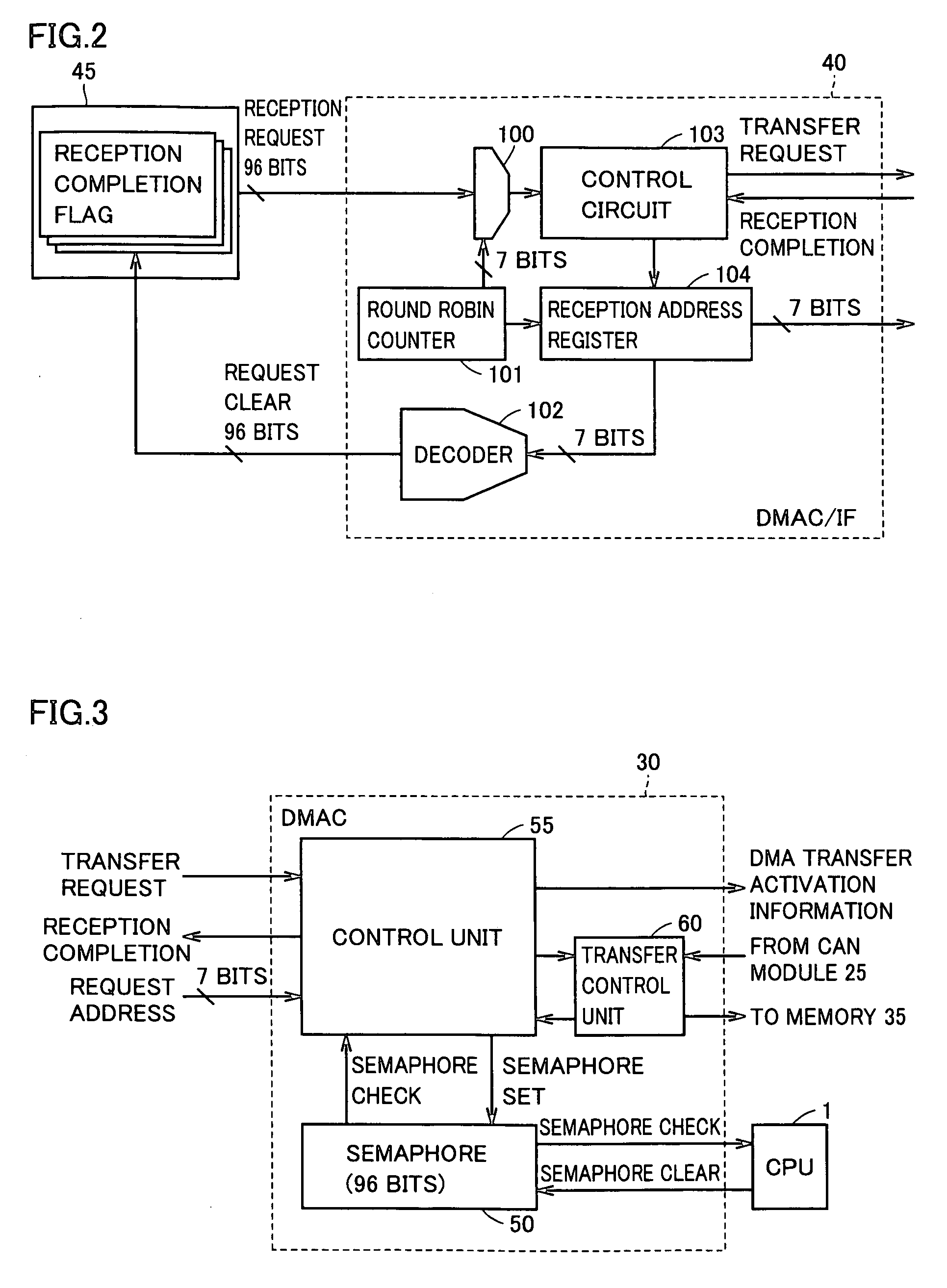
[0059]With reference to FIG. 5, a DMAC / IF 40# according to a second embodiment of the present invention is structured to have not a round robin counter but a priority encoder unit 110.

[0060]More specifically, as compared with DMAC / IF 40 described in FIG. 2, priority encoder unit 110 is provided in place of selector 100 and round robin counter 101.

[0061]Priority encoder unit 100 generates a preferential address based on priority and outputs the same to reception address register 104 in response to a 96-bit reception request signal. Reception address register 104 receives and holds the address output from priority encoder unit 110. Priority encoder unit 110 also notifies control circuit 103 in response to the reception request signal from the message box unit. Control circuit 103 outputs a transfer request signal to DMAC unit 30 in response to the reception notification from priority encoder unit 110. In addition, control circuit 103 controls reception address register 104 to output a...


PUM


Abstract

A CAN module receives a message from a CAN bus to store the same in a message box unit of a message box. A reception request signal is output from the message box unit to a DMAC / IF. The DMAC / IF outputs a 7-bit encoded address together with a transfer request signal. A DMAC accesses a selected message box unit of the CAN module and a memory based on the transfer request signal and the 7-bit encoded address to transfer the message stored in the selected message box unit to the memory.

Description

BACKGROUND OF THE INVENTION[0001]1. Field of the Invention[0002]The present invention relates to data transfer control of an information processing device and, more particularly, a direct memory access control system.[0003]2. Description of the Background Art[0004]In a conventional information processing device having a central processing unit, a main storage device and an I / O apparatus connected through a bus, when data transfer occurs with the I / O apparatus, the central processing unit issues an instruction to the I / O apparatus to execute processing of transferring information from the I / O apparatus to the main storage device through the bus.[0005]In such a case, the central processing unit (CPU) should constantly monitor the I / O apparatus under its control to wait for the completion of the data transfer operation, so that load on the CPU might be increased to degrade performance of the system as a whole. In recent years, therefore, adopted for data transfer control is a direct me...

Claims


Application Information

Patent Timeline
Patent Type & Authority Patents(United States)
IPC IPC(8): G06F13/14G06F13/00
CPCG06F13/28
Inventor INOUE, HIDEOMINEMATSU, ISAOIKENOBE, TAKAHIRO
Owner RENESAS ELECTRONICS CORP
Learn More