Apparatus for tilting and securing a heat exchanger

a technology for supporting and heat exchangers, applied in indirect heat exchangers, lighting and heating apparatus, machines/engines, etc., can solve the problem of limiting the space for the placement of the supporting structure of these heat exchangers

Inactive Publication Date: 2008-05-13
BLUE LEAF I P INC
View PDF18 Cites 32 Cited by
  • Summary
  • Abstract
  • Description
  • Claims
  • Application Information

AI Technical Summary

Benefits of technology

[0007]According to another preferred aspect of the invention, the heat exchanger has a center of gravity disposed between the air flow surfaces thereof, and the heat exchanger is mounted to the vehicle for pivotal movement about a side-to-side extending axis located or offset a predetermined distance from the center of gravity in the first direction, such that when the heat exchanger is in the first pivotal position, gravity or its own weight will create a moment about the pivot joint which will act to urge it to pivot in the second direction, to help hold or retain the heat exchanger in the first position and oppose forces in the opposite direction resulting from jarring and the like that may urge the heat exchanger in the opposite direction. The arm also preferably includes an element positioned to abut the heat exchanger when in the first position and the arm is positioned beside the heat exchanger, for further holding it in that position, and for damping and limiting vibration of the heat exchanger and the arm. Such element can include a resilient pad contacting the heat exchanger for cushioning and vibration reduction. Such element can also be positioned and oriented for applying a force against the heat exchanger in the first direction when the arm is pivoted in that direction from its position beside the heat exchanger, for initiating the pivotal movement of the heat exchanger toward the second pivotal position. Still further, the arm is preferably of sufficient length such that the tilt angle of the second pivotal position relative to the first pivotal position can be between about 20° and about 60°, to provide sufficient space for inspecting and accessing aspects of the heat exchanger for cleaning, servicing, maintenance and other purposes.

Problems solved by technology

There are also space restrictions under the shroud or hood of a tractor where the air conditioning condenser and charge air cooler are to be located, and also restrictions therebelow, which limit the available space for placement of supporting structure for these heat exchangers.

Method used


Image

  • Apparatus for tilting and securing a heat exchanger
  • Apparatus for tilting and securing a heat exchanger
  • Apparatus for tilting and securing a heat exchanger

Examples


Embodiment Construction

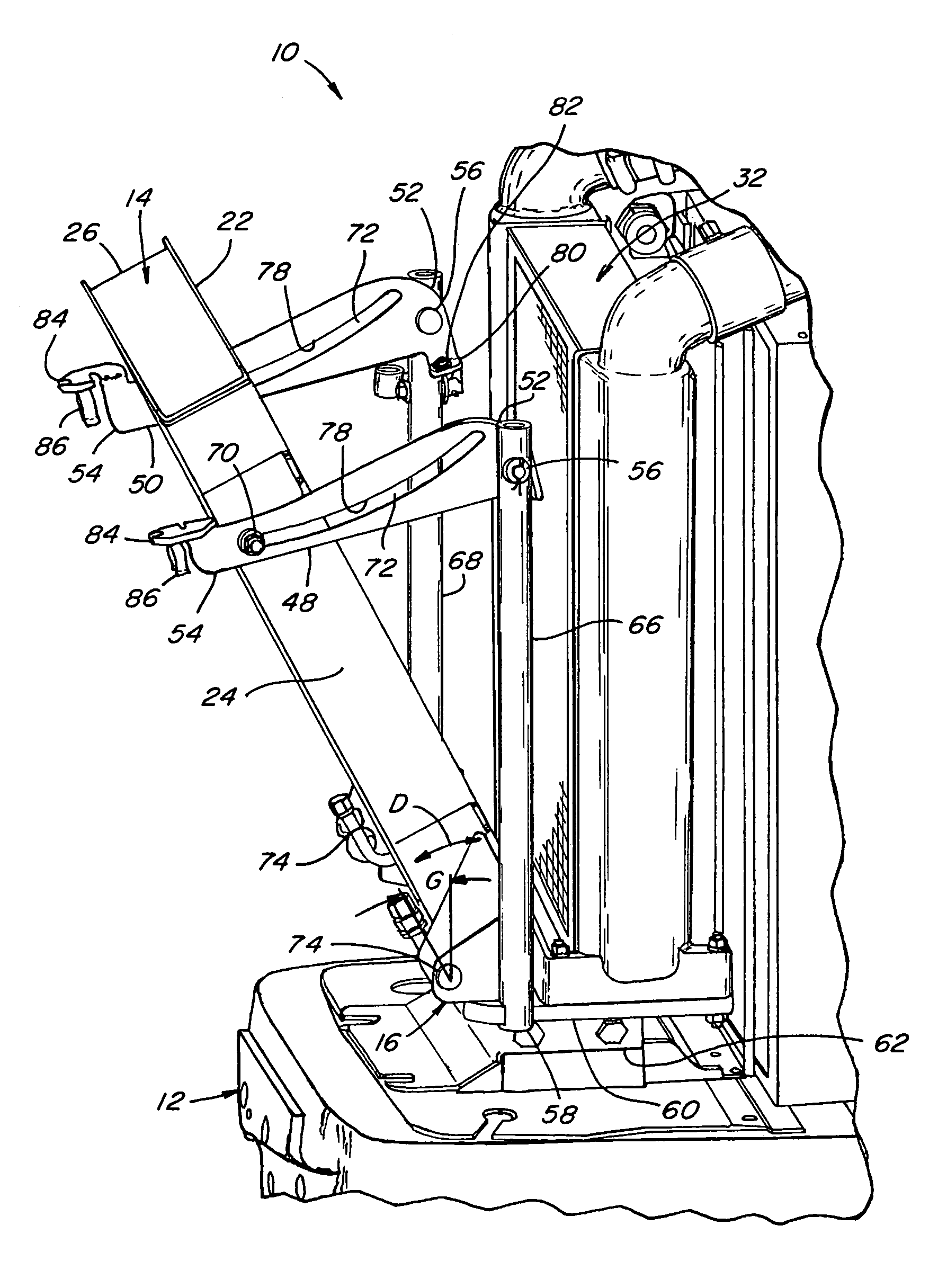
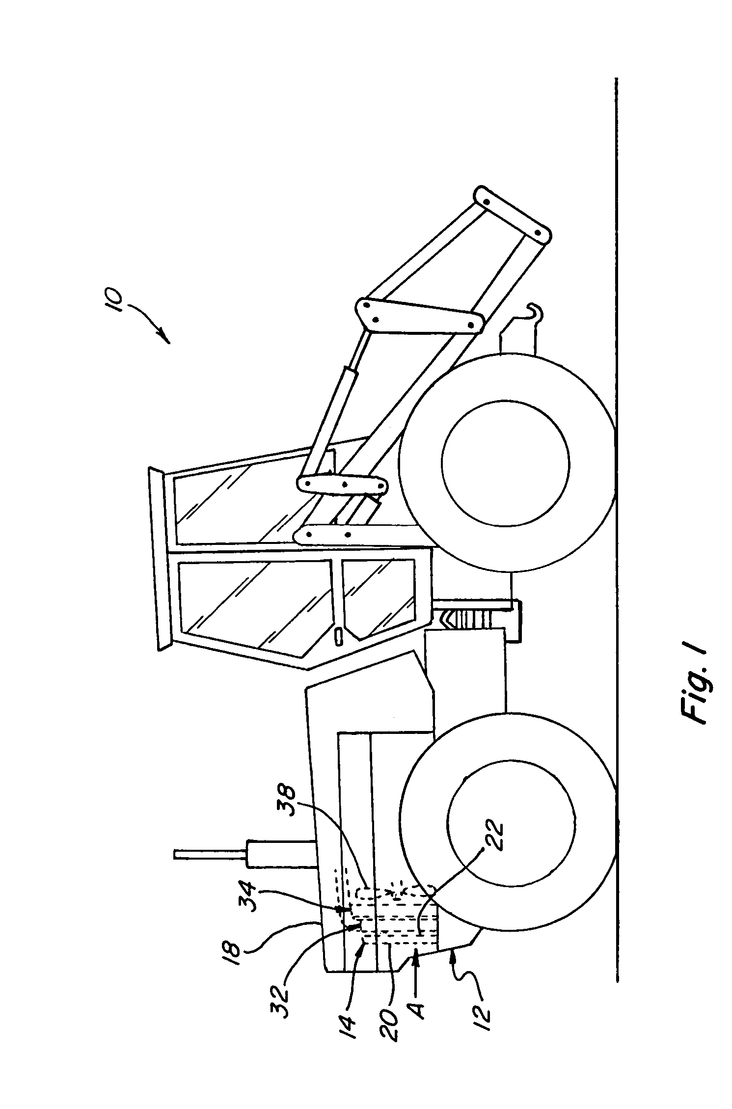
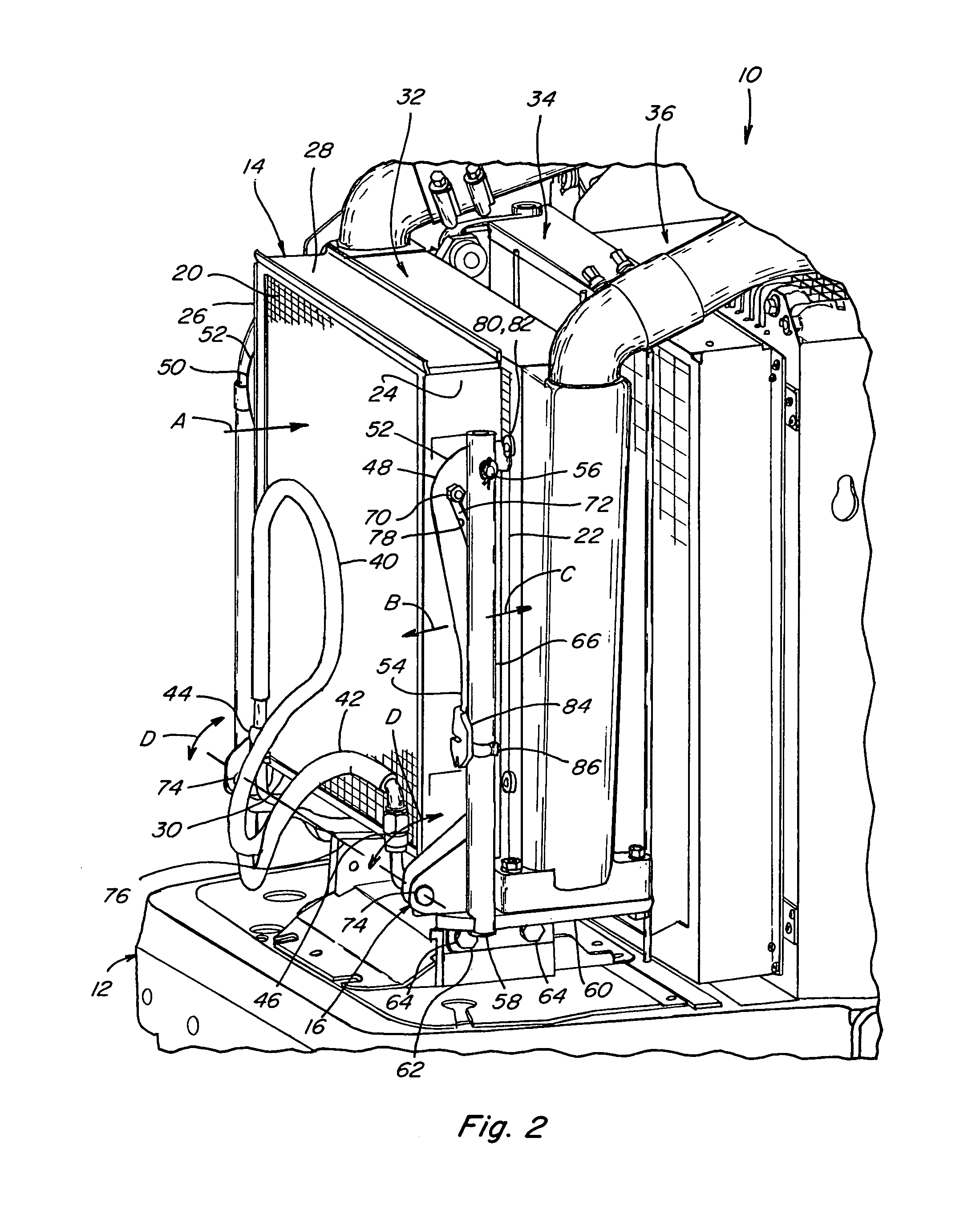
[0016]Referring to FIGS. 1 and 2, a vehicle, which is a bi-directional tractor 10, is shown, including an end 12 having a heat exchanger 14 mounted and supported for pivotal movement by apparatus 16 (FIG. 2) constructed and operable according to the teachings of the present invention. Bi-directional tractor 10 is representative of a wide variety of vehicles, particularly work machines, such as tractors for agricultural, construction, and mining purposes, with which the present invention can be used. Heat exchanger 14 is shown mounted on end 12 within a space defined by an outer hood 18 (shown removed in FIG. 2). Heat exchanger 14 is depicted as a conventional condenser of an air conditioning system of tractor 10, and includes a generally planar first air flow surface 20 facing in a first longitudinal direction of tractor 10, and an oppositely facing second air flow surface 22, for the flow of air through heat exchange 14, in the conventional, well known manner. Heat exchanger 14 add...


PUM


Abstract

Apparatus for supporting a heat exchanger such as a condenser of an air conditioning system on a vehicle, for pivotal movement between an operational position and a position angularly related to the operational position, for such purposes as inspection, cleaning, service and maintenance, the apparatus being configured for holding the heat exchanger in the operational position, and for guiding and controlling movement thereof to the tilted position, and holding the heat exchanger in the tilted position.

Description

TECHNICAL FIELD[0001]This invention relates generally to apparatus for supporting a heat exchanger such as a condenser of an air conditioning system on a vehicle, for pivotal movement between an operational position and a tilted position angularly related to the operational position, for such purposes as inspection, cleaning, service and maintenance, and more particularly, to apparatus configured for holding the heat exchanger in the operational position, and for guiding and controlling movement thereof to the tilted position, and holding the heat exchanger in the tilted position.BACKGROUND ART[0002]Heat exchangers, such as condensers of air conditioning systems, charge air coolers, and radiators for engines, may require from time to time, inspection, cleaning, maintenance and repair. In particular, for vehicles such as work machines and tractors, cleaning of debris such as dirt and airborne crop material from the heat exchanger may be required during the operation of the work machi...

Claims


Application Information

Patent Timeline
Patent Type & Authority Patents(United States)
IPC IPC(8): B60K11/04F01P11/08
CPCF28D1/0435F28F9/002F28F2280/10Y10T292/289Y10T292/291
Inventor RASSET, JOHN T.LARSON, JAY M.
Owner BLUE LEAF I P INC
Why Eureka
Try Eureka