

Acetabular component of total hip replacement assembly
a technology of acetabular parts and total hip replacement, which is applied in the direction of hip joints, internal osteosynthesis, medical science, etc., can solve the problems of continuing number, and achieve the effect of reducing the amount of extra bone resection and extending the reamed surface of bon
- Summary
- Abstract
- Description
- Claims
- Application Information
AI Technical Summary
Benefits of technology
Problems solved by technology
Method used
Image

Examples
Embodiment Construction
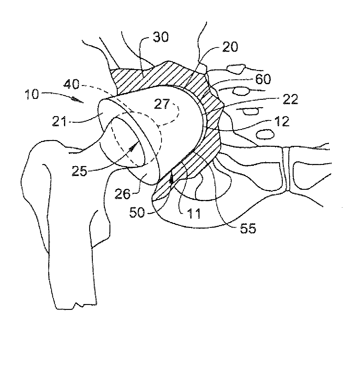
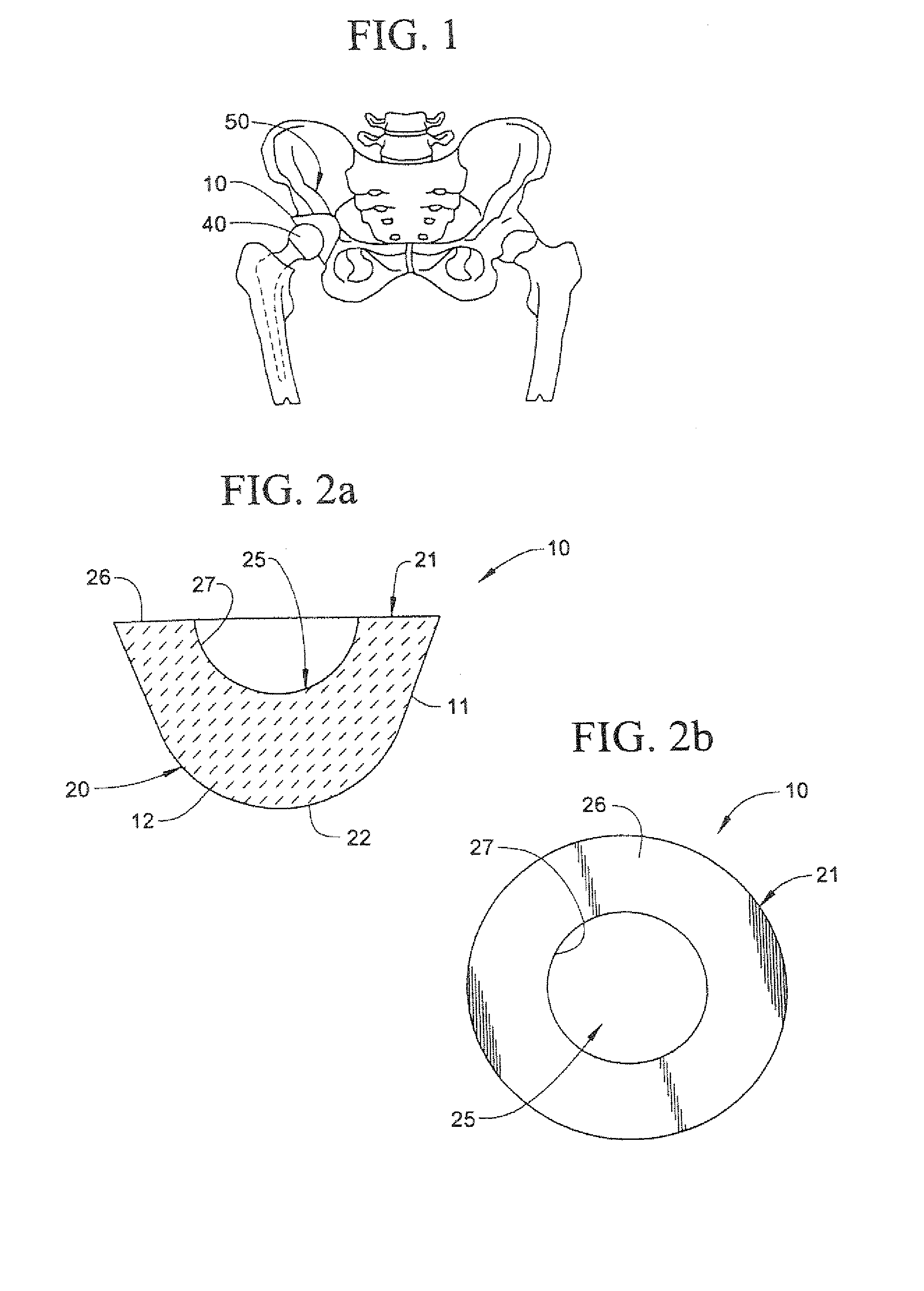
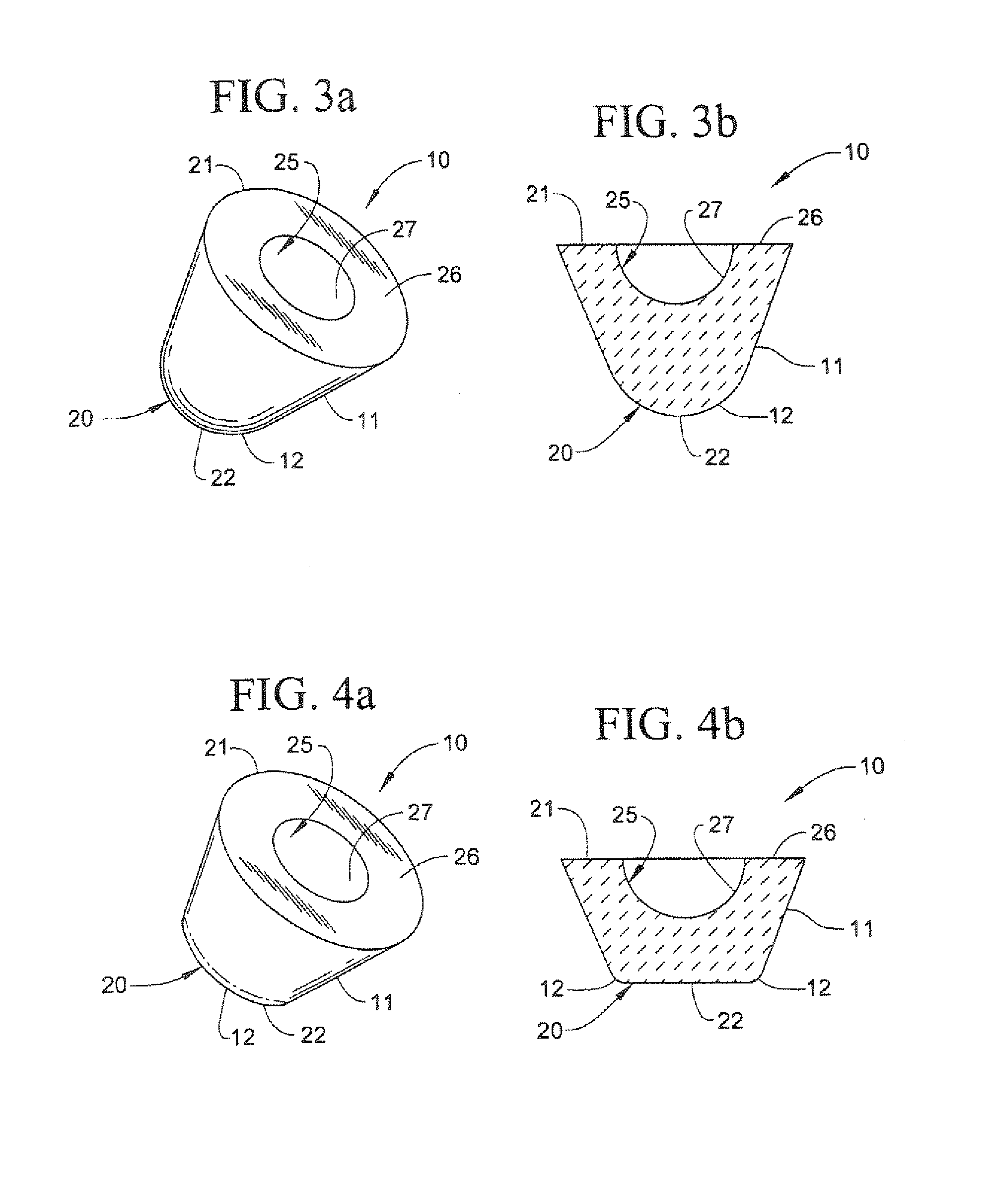
[0011]In a first aspect, the present invention consists in a device for use in surgical procedures involving arthroplasty, the device including a socket member having a first surface and a second bone engaging surface, the first surface including at least a bearing surface adapted to receive a counter-component of a joint, and the bone engaging surface including a first portion having a shape, and at least a second portion having a different shape to that of the first portion.
[0012]In a second aspect, the present invention consists in a method of inserting a device according to the first aspect during an arthroplasty procedure, the method including the steps of:
[0013]a) bringing a surface of an appropriate joint orientation determining means into apposition with the exposed surface of the socket portion of a joint;
[0014]b) manipulating the joint orientation determining means so that the correct angular orientation for a socket portion of a joint replacement assembly is determined;
[0...
PUM
| Property | Measurement | Unit |
|---|---|---|
| Thickness | aaaaa | aaaaa |
| Diameter | aaaaa | aaaaa |
| Diameter | aaaaa | aaaaa |
Abstract
Description
Claims
Application Information