Apparatus for estimating direction of arrival wave

a technology of arrival wave and approximation method, applied in the direction of multi-channel direction-finding system using radio waves, instruments, computation using denominational number representation, etc., can solve the problems of unfavorable operation, unfavorable operation, and inability to accurately estimate the arrival wave from the eigenvalue, so as to improve the operation efficiency

Active Publication Date: 2008-05-13
DENSO IT LAB +1
View PDF2 Cites 12 Cited by
  • Summary
  • Abstract
  • Description
  • Claims
  • Application Information

AI Technical Summary

Benefits of technology

[0032]According to this aspect of the invention, the implementation of the Householder transformation operation on the column, which does not correspond to a signal, credibility of which is low in computed result, can be saved by properly setting the threshold value since in the Householder transformation operation, further Householder transformation operation is not implemented if the maximum value of the column norms to be computed from the matrix for obtaining the eigenvalue is the same as or lower than a predetermined threshold value, thereby extremely preventing the implementation of the vain eigenvalue decomposition operation.
[0057]According to this aspect of the invention, it is possible to prevent implementation of the Householder transformation operation on the matrix portion, on which no Householder transformation operation has been implemented in the last operation cycle due to the underflow, in order to improve the operation efficiency.

Problems solved by technology

If a fixed decimal mode is used for a word size which is insufficient for an operation, the above-mentioned inconvenience is especially ready to appear.
If the credibility on the eigenvalues is low, the number of arrival waves which is estimated from the eigenvalues is likely to be incorrect.
In addition, the vain operation is repeated in the eigenvalue decomposition operation in order to finally obtain the eigenvalue having low credibility, so that unnecessary operation is loaded on a processing unit.

Method used


Image

  • Apparatus for estimating direction of arrival wave
  • Apparatus for estimating direction of arrival wave
  • Apparatus for estimating direction of arrival wave

Examples


Embodiment Construction

[0058]An embodiment of the invention will now be explained, referring to appended drawings.

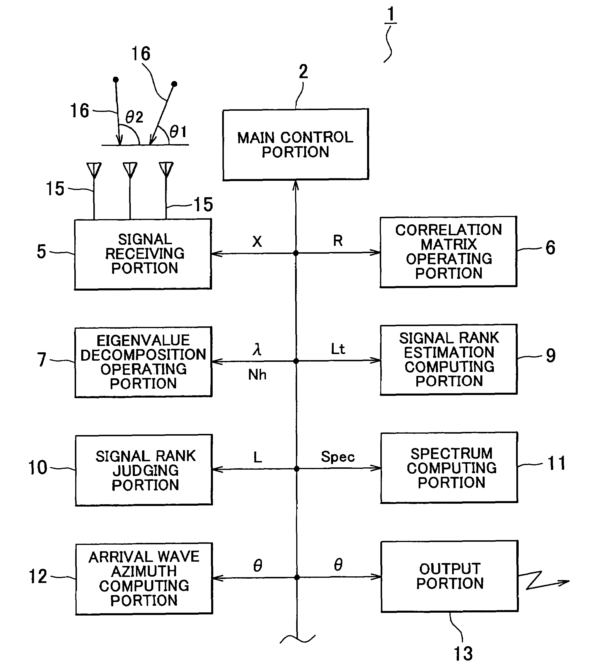
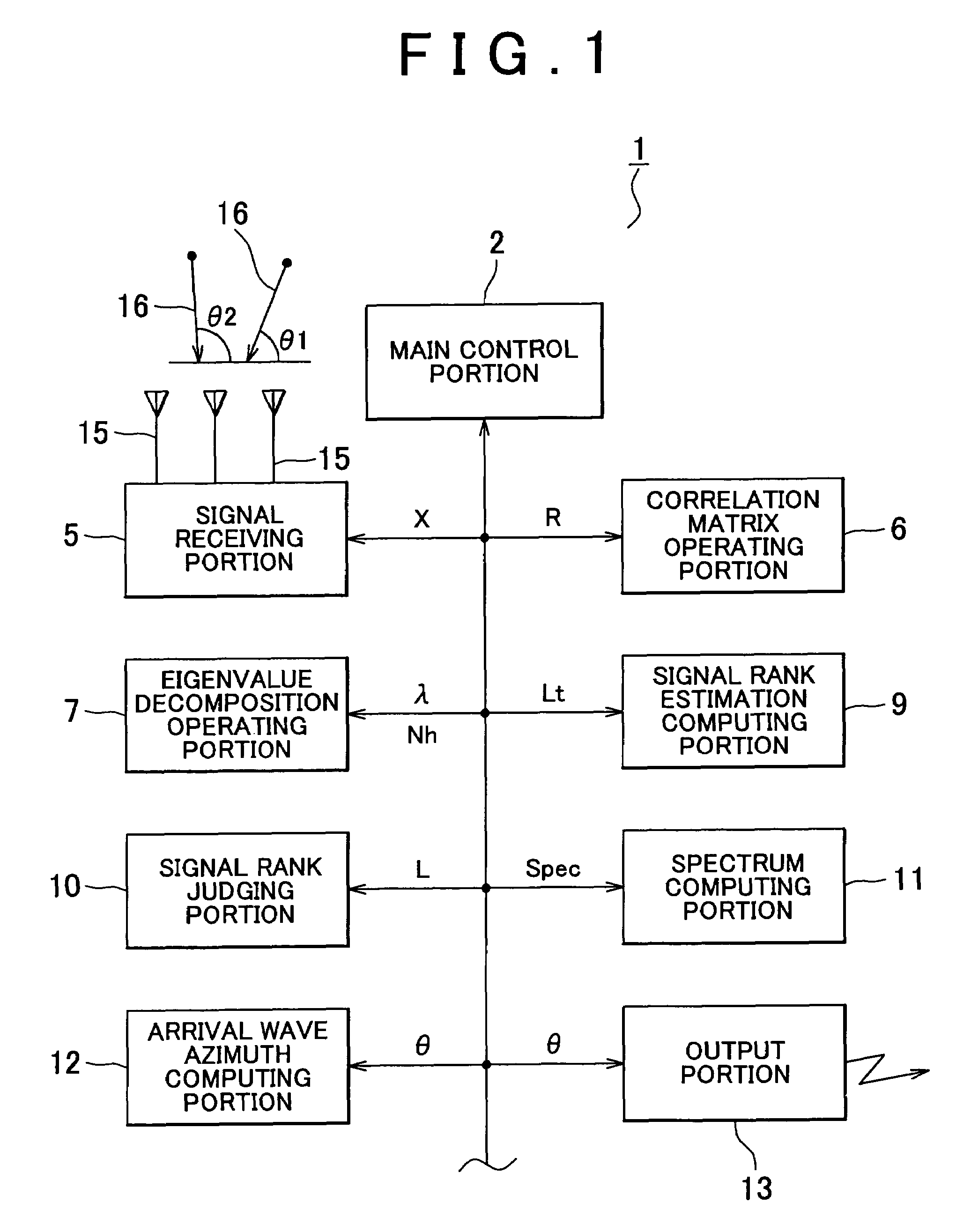
[0059]An apparatus for measuring azimuth of arrival wave 1 has a main control portion 2, as shown in FIG. 1. A signal receiving portion 5, a correlation matrix operating portion 6, an eigenvalue decomposition operating portion 7, a signal rank estimation computing portion 9, a signal rank judging portion 10, a spectrum computing portion 11, an arrival wave azimuth computing portion 12, and an output portion 13 are connected with the main control portion 2 via a bus line 3. The signal receiving portion 5 is provided with K numbers (two or more) of antennas 15.

[0060]The apparatus for measuring azimuth of arrival wave 1 of FIG. 1 is merely illustrative. The respective elements within enclosures in FIG. 1 may be replaced by a CPU (central processing unit) comprising a computer and proper memories, and program for activating a computer. In such a case, a computer functions as the elements comprisin...


PUM


Abstract

Apparatus and method are disclosed for estimating direction of an arrival wave, such as radio or acoustic waves. A correlation matrix of an arrival wave is computed, and matrices for obtaining eigenvalues and eigenvectors are produced. Column norms of the matrix, which is subject to a Householder transformation, are computed. Whether a maximum value of the column norms is the same as or lower than a predetermined threshold is judged. A Householder transformation of the matrix is performed only if the maximum value of the column norms is determined to be greater than or equal to the threshold, and not when the maximum value of the column norms is less than the threshold. The eigenvectors and the eigenvalues of the correlation matrix are obtained by further implementing the Householder transformation. The number of arrival waves is judged from the number of times the Householder transformation is performed.

Description

BACKGROUND OF THE INVENTION[0001]This invention relates to an apparatus for estimating direction of arrival wave, such as radio wave and acoustic wave, which arrives at a plurality of antenna elements.[0002]A technique of estimating arrival directions of one or more arrival waves, such as radio waves and acoustic waves, of the same frequency which are caught by two or more antenna elements is well known. As one of such methods, MUSIC (Multiple Signal Classification) method is well known (see Japanese patent application the publication number of which is 2000-121716.[0003]In MUSIC method, on the basis of a signal data vector of arrival waves, a correlation matrix thereof is obtained, and an eigenvalue decomposition operation for decomposing the obtained correlation matrix into eigenvectors and eigenvalues is implemented, and azimuths of the arrival waves are estimated from the thus obtained eigenvectors. In order to obtain the arrival azimuth, it is necessary to estimate the number o...

Claims


Application Information

Patent Timeline
Patent Type & Authority Patents(United States)
IPC IPC(8): G01S5/02G01S3/46G01S3/74
CPCG01S3/74G01S3/8006
Inventor SHIRAI, HIDEKINATSUME, KAZUMA
Owner DENSO IT LAB
Why Eureka
Try Eureka