Optical pattern generator using a single rotating component

a technology of optical pattern generator and rotating component, which is applied in the field of optical pattern generator using a single rotating component, can solve the problems of limiting the scan rate, unsuitable for certain applications, and restricting the patterns that can be generated, and achieves high radiometric efficiency, convenient rotation, and high speed

Active Publication Date: 2008-05-13
SOLTA MEDICAL
View PDF128 Cites 30 Cited by
  • Summary
  • Abstract
  • Description
  • Claims
  • Application Information

AI Technical Summary

Benefits of technology

[0013]This approach can result in many advantages. The use of a single rotating component with sectors that are positioned contiguously around its periphery can provide a high radiometric efficiency. The geometry of a rotating component such as a thin disk with optical elements located on the periphery facilitates rotation at high angular velocities, thus producing image patterns at high rates of speed. The angular velocity of the rotating component combined with the pseudo-stationary angular deflection can be used to cause the individual image points, spots, or lines to deliver high radiant energy doses to a small point in the image space with high radiometric efficiency. The angular deflection is pseudo-stationary in the sense that each deflection sector produces an approximately constant angular deflection as it rotates through the incident optical beam, but each deflection sector can have a different constant angular deflection.
[0023]In an embodiment based on this geometry, sectors comprise two mirrors in a ‘Z-folded’ arrangement that causes the exit optical beam to be approximately collinear to the incident optical beam. Each sector can have a different included angle between the mirrors in the sector, such that different sectors cause different angular deflections. The two mirrors can be planar or they can be sections of larger parent surfaces of revolution such as spheres or aspheres. Angular deflection can be maintained at a nearly constant level by making the optical axes of each mirror surface coincident with the rotation axis of the disk so that rotation of the disk does not change the form of the optical surfaces presented to the incident optical beam.

Problems solved by technology

However, optical pattern generators based on tilting mirrors typically have characteristics that make them unsuitable for certain applications.
This takes time, which limits the scan rate.
However, this severely restricts the patterns that can be generated.
For example, it is difficult to generate irregular patterns since the mirror motion is constrained to be oscillatory.
The near-resonance condition also limits the range of scan rates that can be achieved.
For example, it,is difficult to tune such a system over a wide range of scan rates since the near-resonance condition cannot be met over a wide range.
In addition, the angular scan velocity of resonant scanners is usually sinusoidal and not suitable for a large number of applications where dwell time at each point must be reasonable constant.
As a result of these characteristics, galvanometer-based systems and convex polygon systems are not well suited for high speed pattern generation, particularly if the pattern is an irregular or a sparse one.
However, the rotating polygon approach also has drawbacks that make it unsuitable for certain applications.
For example, systems that produce a series of scan lines can suffer from aberrations due to the rotation.
This can cause changes in the amount of offset and / or other unwanted aberrations.
Scan line bow and other effects caused by rotation can cause additional problems, depending on the application.
If this motion is slow compared to the dwell time of the optical beam on the target, then the bow effectively introduces an unwanted motion in the perpendicular direction.

Method used


Image

  • Optical pattern generator using a single rotating component
  • Optical pattern generator using a single rotating component
  • Optical pattern generator using a single rotating component

Examples


Embodiment Construction

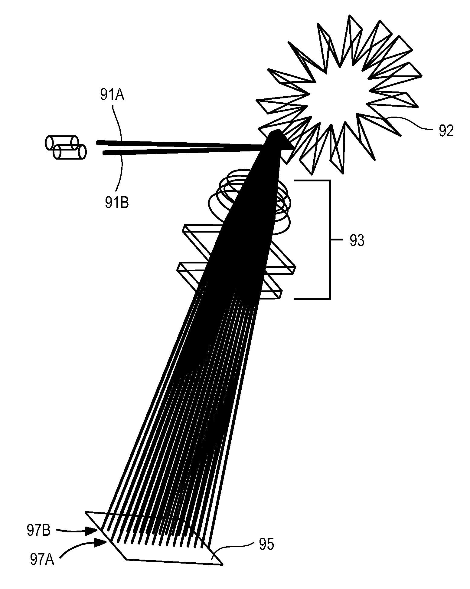
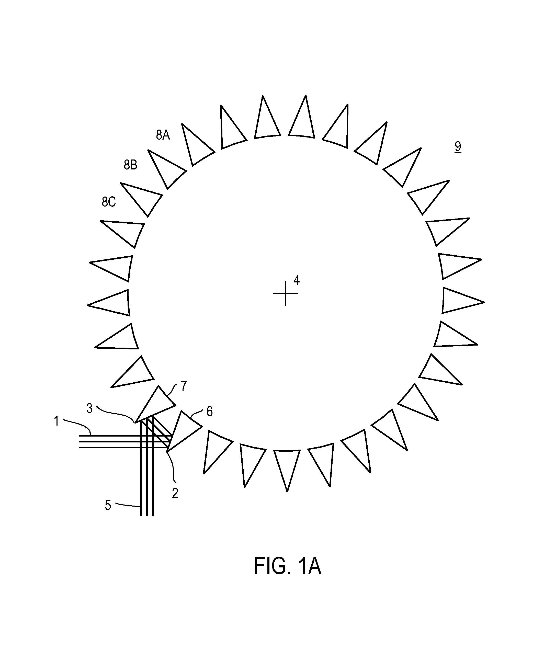
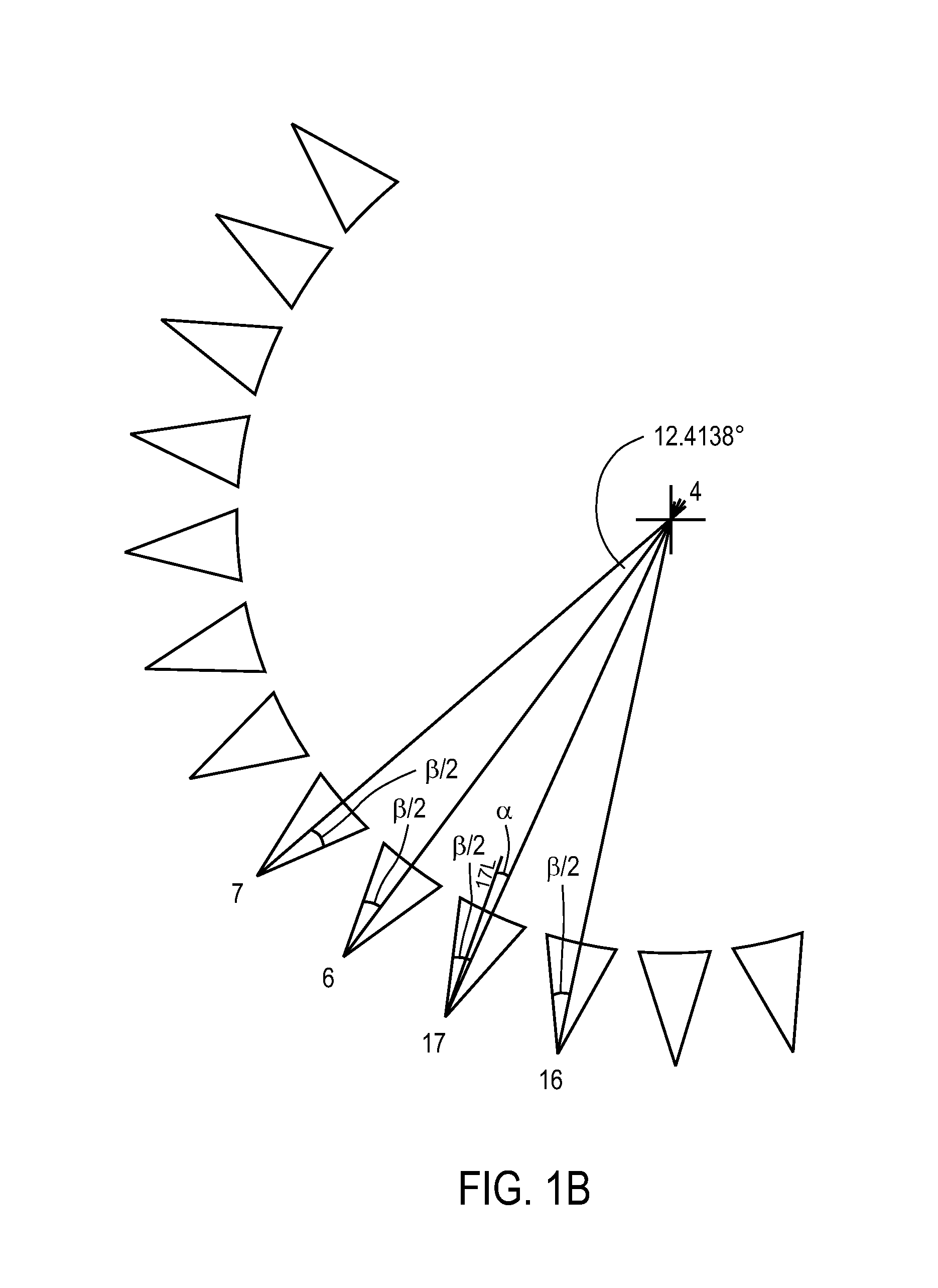
[0040]FIG. 1A is a side view of an optical pattern generator according to the invention, where the incident optical beam 1 lies substantially in the plane of rotation of rotatable component 9. In this example, the rotating component 9 is divided into twenty nine sectors 8A, 8B, 8C, etc., which are arranged in a circle centered on the rotation axis 4 of the rotating component 9. The incident optical beam 1 propagates along a direction that lies in the plane of rotation. Each sector 8 includes a pair of reflective elements (e.g., reflective surfaces 2 and 3 for the sector that is currently active). The surface normals of the reflective surfaces have a substantial component in the plane of rotation. In this example, the rotating component 9 includes prisms 6, 7, etc. that are arranged in a circle. The faces of the prisms are reflectively coated and the reflectively coated surfaces from adjacent prisms (e.g., reflective surfaces 2 and 3 from prisms 6 and 7) form the opposing reflective ...


PUM


Abstract

An optical pattern generator uses a single rotating component. The rotating component includes a number of deflection sectors. Each sector deflects an incident optical beam by a substantially constant angular amount although this amount may vary from one sector to the next. The rotating component may be combined with an imaging lens group that produces, for example, image points, spots, or lines displaced along a line locus.

Description

CROSS-REFERENCE TO RELATED APPLICATION(S)[0001]This application claims priority under 35 U.S.C. § 119(e) to U.S. Provisional Patent Application Ser. No. 60 / 652,891, “High Efficiency, High Speed Optical Pattern Generator Using a Single Rotating Component,” filed Feb. 14, 2005; and is a continuation-in-part of U.S. patent application Ser. No. 10 / 750,790, “High Speed, High Efficiency Optical Pattern Generator Using Rotating Optical Elements,” filed Dec. 31, 2003. The subject matter of all of the foregoing are incorporated herein by reference in their entirety.BACKGROUND OF THE INVENTION[0002]1. Field of the Invention[0003]This invention relates generally to optically generating a pattern of figures such as arrays of image points, spots, or lines. More particularly, this invention relates to generating such patterns using a single rotating component that has a plurality of deflection sectors that deflect an incident optical beam by various amounts.[0004]2. Description of the Related Art...

Claims


Application Information

Patent Timeline
Patent Type & Authority Patents(United States)
IPC IPC(8): G02B26/08B41J2/435B41J2/47G02B26/10
CPCB41J2/471G02B26/12G02B26/10B41J2/435
Inventor BROOME, BARRY G.DEBENEDICTIS, LEONARD CFRANGINEAS, GEORGE
Owner SOLTA MEDICAL
Why Eureka
Try Eureka