Electronics equipment heat exchanger system

a technology of heat exchanger and electronic equipment, which is applied in the direction of lighting and heating equipment, electrical equipment, cooling/ventilation/heating modifications, etc., can solve the problems of difficult to anticipate (1) future additions of computer servers and (2) future advances of computer servers that produce increased heat, and achieve the effect of reducing the thermal management requirements of the server room hvac system

Active Publication Date: 2008-05-13
PARKER INTANGIBLES LLC
View PDF12 Cites 82 Cited by
  • Summary
  • Abstract
  • Description
  • Claims
  • Application Information

AI Technical Summary

Benefits of technology

[0016]An additional object is to provide an electronics equipment heat exchanger system that reduces the thermal management requirements for a server room HVAC system.

Problems solved by technology

Performance in any computer server is typically limited by the performance of the server room's cooling systems rather than by the performance of the computer servers.
One problem with conventional server room thermal management systems is that the HVAC systems are typically designed to support only up to a pre-specified number of watts per square foot (e.g. 100 watts per square foot) a formula which makes it difficult to anticipate (1) future additions of computer servers and (2) future advances in computer servers that produce increased heat.
In addition, while liquid thermal management systems are highly efficient in removing heat from computer services, they do not remove all heat generated by a computer server (e.g. from the non-liquid cooled components) thereby still requiring an efficient air conditioning system to maintain a desired air temperature within the server room.
If the HVAC system cannot thermally manage the air within the server room, then additional computer servers cannot be added to the server room when space is available.

Method used


Image

  • Electronics equipment heat exchanger system
  • Electronics equipment heat exchanger system
  • Electronics equipment heat exchanger system

Examples


Embodiment Construction

A. Overview

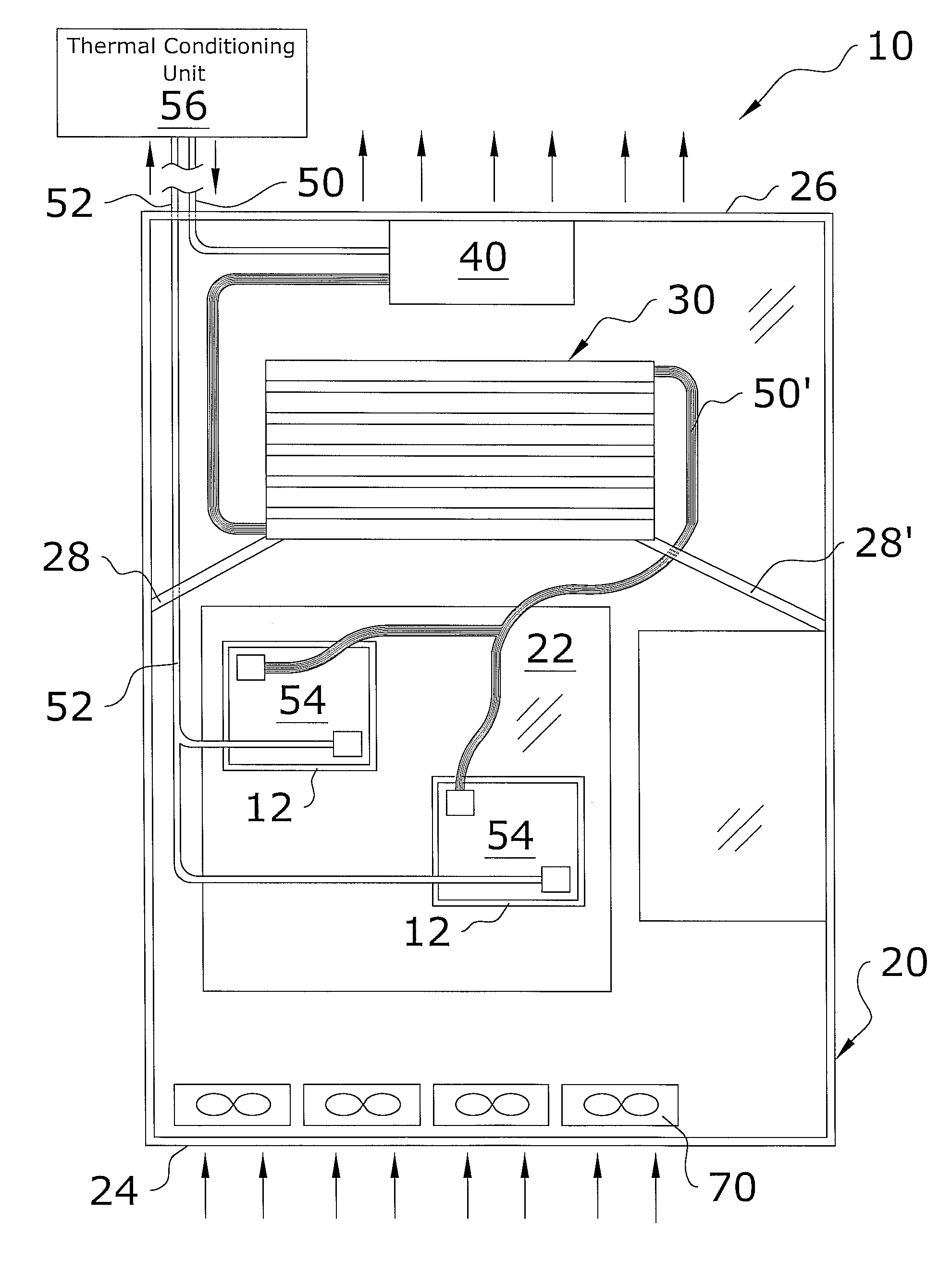
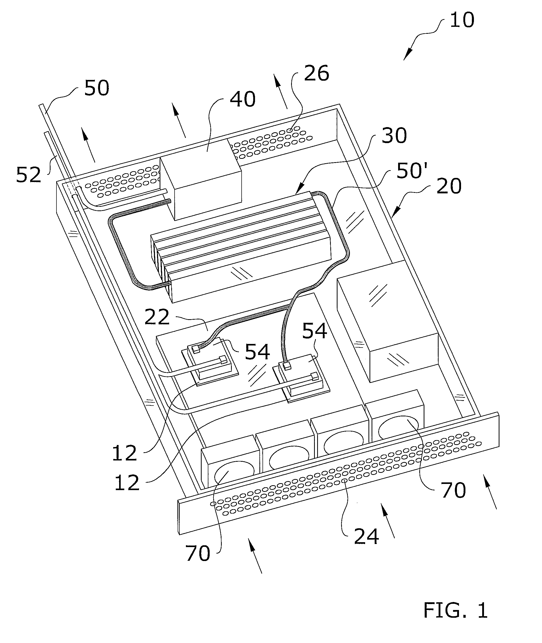
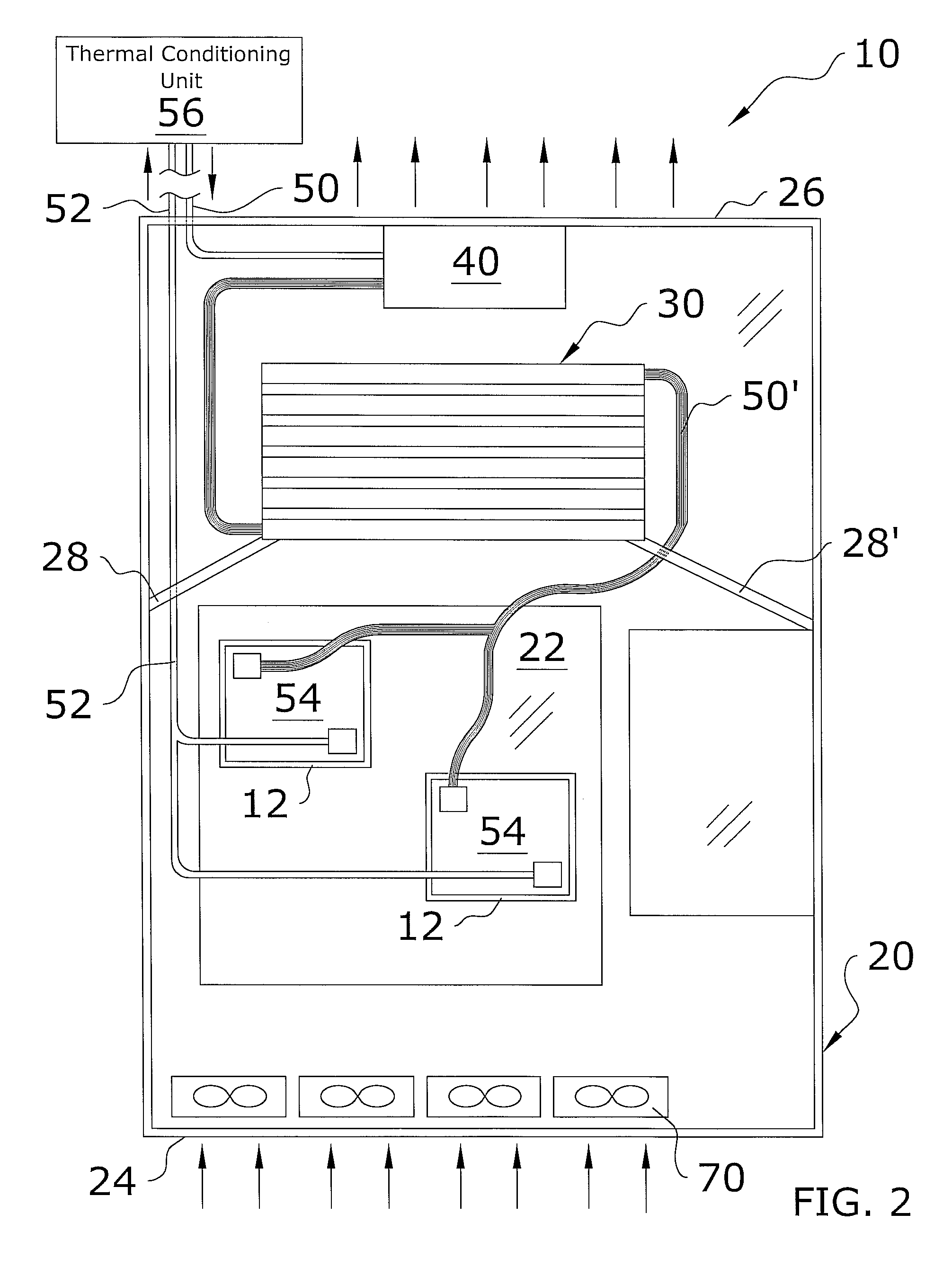
[0030]Turning now descriptively to the drawings, in which similar reference characters denote similar elements throughout the several views, FIGS. 1 through 9 illustrate an electronics equipment heat exchanger system 10, which comprises a heat exchanger 30 attached near an air outlet 26 of a support unit 20 for a support rack 60, a thermal management unit 54 fluidly connected to the heat exchanger 30, and a thermal conditioning unit 56 fluidly connected to the thermal management unit 54 and the heat exchanger 30. The thermal management unit 54 directly thermally manages one or more electronic devices of the server mainboard 22 while the heat exchanger 30 thermally manages the exhaust air before the exhaust air exits through the outlet of the support unit 20 of the computer server.

B. Support Rack

[0031]FIG. 5 illustrates an exemplary support rack 60. The support rack 60 may be comprised of various types of structures capable of supporting one or more computer servers (or ot...


PUM


Abstract

An electronics equipment heat exchanger system for thermally managing the electronic devices of a computer server and the exhaust air emitted from the computer server. The electronics equipment heat exchanger system generally includes a heat exchanger attached near an air outlet of a support unit for a support rack, a thermal management unit fluidly connected to the heat exchanger, and a thermal conditioning unit fluidly connected to the thermal management unit and the heat exchanger. The thermal management unit directly thermally manages one or more electronic devices of the server mainboard while the heat exchanger thermally manages the exhaust air before the exhaust air exits through the outlet of the support unit of the computer server.

Description

CROSS REFERENCE TO RELATED APPLICATIONS[0001]Not applicable to this application.STATEMENT REGARDING FEDERALLY SPONSORED RESEARCH OR DEVELOPMENT[0002]Not applicable to this application.BACKGROUND OF THE INVENTION[0003]1. Field of the Invention[0004]The present invention relates generally to server room thermal management devices and more specifically it relates to an electronics equipment heat exchanger system for thermally managing the electronic devices of a computer server and the exhaust air emitted from the computer server.[0005]2. Description of the Related Art[0006]Any discussion of the prior art throughout the specification should in no way be considered as an admission that such prior art is widely known or forms part of common general knowledge in the field.[0007]A server room is comprised of one or more computer servers used by a company to perform various functions (e.g. web hosting, cluster computing). Some server rooms are comprised of a “server farm” which includes a s...

Claims


Application Information

Patent Timeline
Patent Type & Authority Patents(United States)
IPC IPC(8): H05K7/00F28D15/00
CPCH05K7/20772H05K7/20836
Inventor TILTON, DONALD E.DAVIDSON, HOWARD L.NETTLETON, NYLES I.
Owner PARKER INTANGIBLES LLC
Why Eureka
Try Eureka