Cable tray support assembly

a cable tray and support technology, applied in the field of raised floor systems, can solve the problems of increasing the cost of installation, affecting the installation effect, and the inability to accommodate the rearrangement of equipment, so as to achieve the effect of reducing material and labor costs

Inactive Publication Date: 2008-05-20
IRVINE ACCESS FLOORS INC
View PDF43 Cites 64 Cited by
  • Summary
  • Abstract
  • Description
  • Claims
  • Application Information

AI Technical Summary

Benefits of technology

[0010]The present invention provides a cable tray support assembly that has lower material and labor costs to install to form a complete raised floor and cable ma...

Problems solved by technology

These electrical power distribution ducts are permanently located within the poured concrete making it impossible to accommodate the rearrangement of equipment as both the use of the floor space changes as well as to accommodate the changes in the equipment due to changes in technology.
With the increased complexity of electronic equipment and the increasing number of pieces of equipment being placed in a single room due to the equipment continuously becoming smaller, the interconnection of these pieces of electronic equipment by communication cables and power cables has become more complex.
The space between the subfloor and the raised panel floor is ...

Method used


Image

  • Cable tray support assembly
  • Cable tray support assembly
  • Cable tray support assembly

Examples


second embodiment

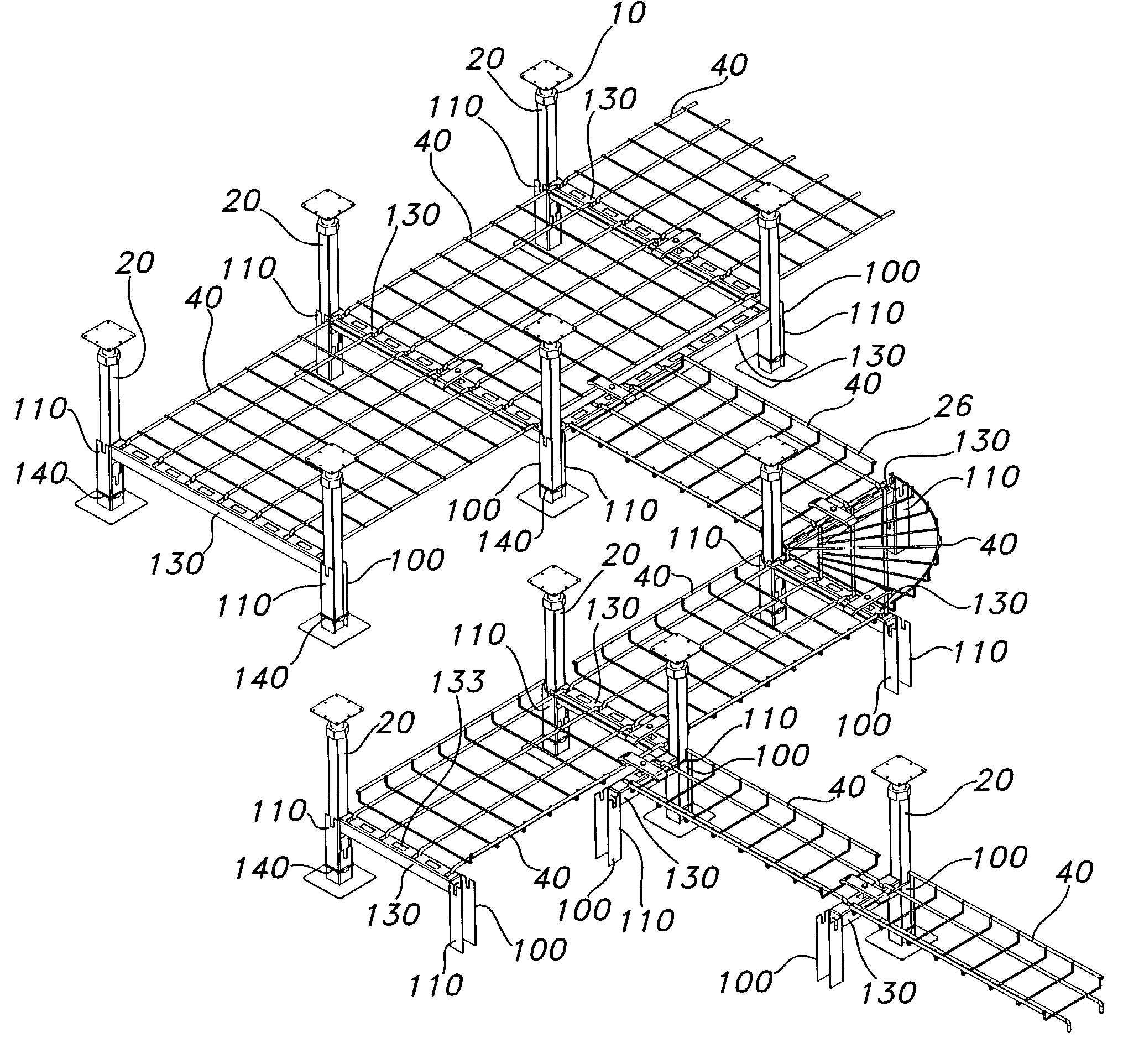
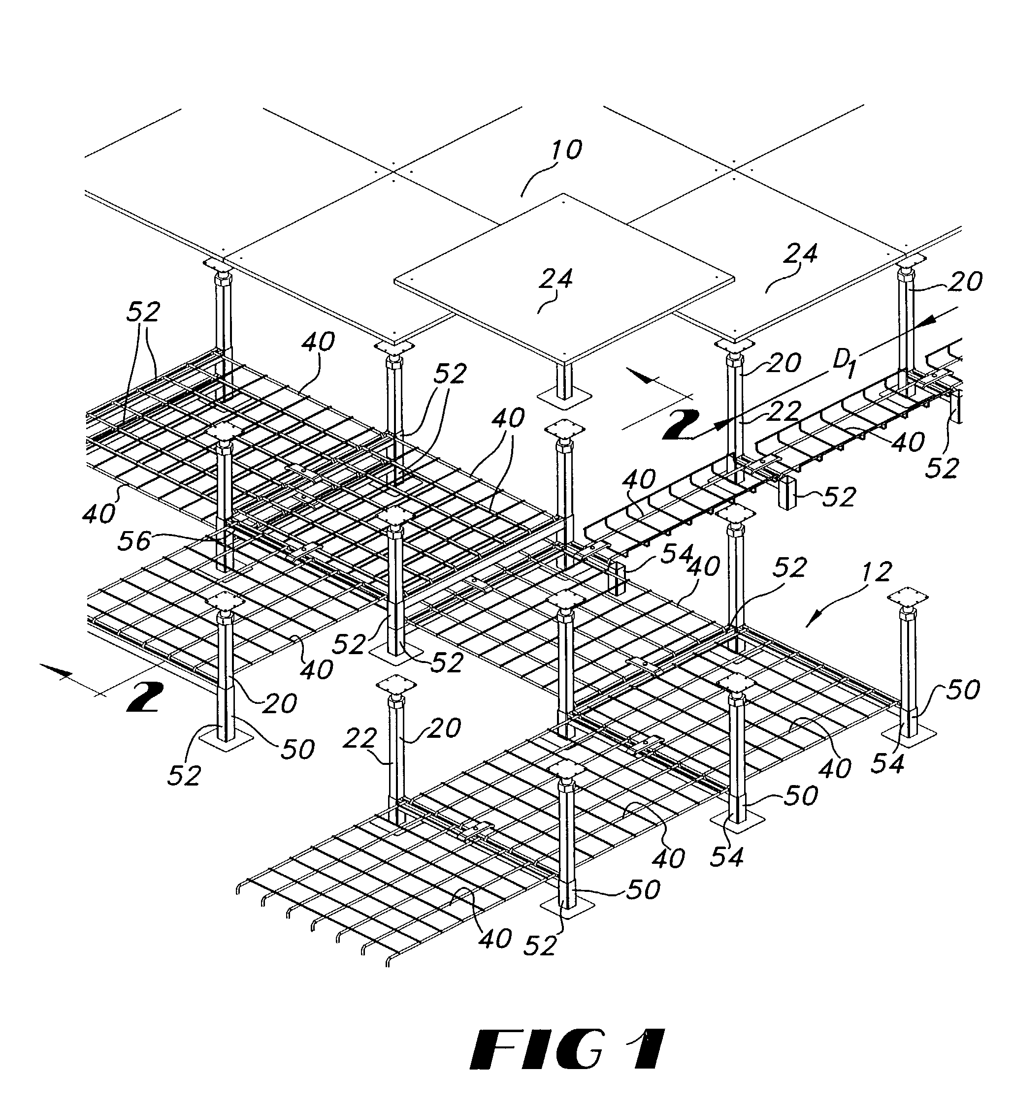
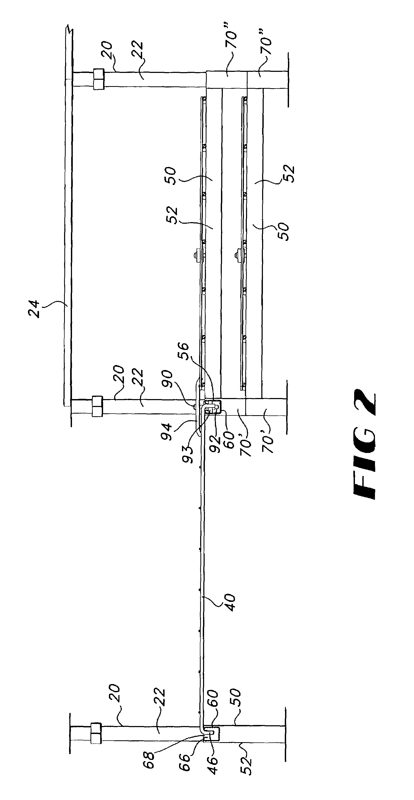
[0042]In the second embodiment, the cable tray assembly may include a second support pedestal 54 having an elongated stringer member 60, an upright sleeve member 70, and a hanger member 80. The sleeve member 70 is connected to a proximal end 62 of the stringer member 60 and defines a bore 76 that extends from a top end 72 to a bottom end 74 of the sleeve member 70. The hanger member 80 is connected to a distal end 64 of the stringer member 60 and has a terminal hook portion 82 that is oriented downwardly away from the horizontally disposed surface 66 of the stringer member 60 and generally parallel to the distal end 64 of the stringer member 60. In cross-section, the terminal hook portion 82 has an inverted “U” shape when inserted for engagement with a sleeve member 70 as discussed below.

[0043]In use, the hanger member 80 of one second support pedestal 54 may be removably connected to a sleeve member 70 of an adjacent first or second support pedestal 52, 54. As one will appreciate, ...

third embodiment

[0046]In the third embodiment, the cable tray assembly 26 may include third support pedestal 56 having an elongated stringer member 60, a first hanger member 80′, and a second hanger member 80″. The first hanger member 80′ is connected to a proximal end 62 of the stringer member 60 and the second hanger member 80″ is connected to a distal end 64 of the stringer member 60. As noted above, each hanger member 80′, 80″ has a terminal hook portion 82 that is oriented downwardly away from the horizontally disposed surface 66 of the stringer member 60 and generally parallel to the respective proximal and distal ends 62, 64 of the stringer member 60.

[0047]In use, the first and second hanger members 80′, 80″ of one third support pedestal 56 may be removably connected to an opposing pair of sleeve members 70 of a pair of opposing support pedestals 50, such as a pair of opposing first support pedestals 52, a pair of opposing second support pedestals 54, or a pair formed from an opposing first ...


PUM


Abstract

A cable tray support assembly for a raised floor system which has a plurality of support pedestals and a platform section. Each support pedestal has an elongated stringer member, a first upright channel member, and an opposing second upright channel member. The stringer member has an opposing pair of flanges depending from the proximal and distal ends of the stringer member. In use, the flanges of the stringer member may be releasably connected to the channel members so that the elongated stringer member is supported above the respective bottom ends of the channel members. At least one of the channel members of each support pedestal may be positioned adjacent to at least a portion of one column to aid in maintaining spatial orientation of the channel member with respect to an upright column. One platform section is suspended from the stringer members of a pair of opposing support pedestals.

Description

[0001]This application is a continuation-in-part of U.S. application Ser. No. 09 / 873,122, filed May 31, 2001, now U.S. Pat. No. 6,672,022 which claims priority to the U.S. provisional application 60 / 208,258, filed May 31, 2000, which is incorporated herein in its entirety.FIELD OF THE INVENTION[0002]The present invention relates to raised floor systems and more particularly to a cable tray support assembly for use in connection with a raised floor system.BACKGROUND OF THE INVENTION[0003]Cable trays in general have been used in power stations and large industrial plants for a number of years to support and route various cables through the plants rather than placing these cables inside a conduit. These cable trays are normally supported from a wall or a ceiling at levels which are above a person's head in order to avoid obstructing normal floor space. An alternative to the elevated cable tray has been elevated distribution ducts which are also normally mounted from a wall or a ceiling...

Claims


Application Information

Patent Timeline
IPC IPC(8): E04B5/48
CPCE04F15/024H02G3/0443H02G3/32
Inventor SIMMONS, GEORGE E.
Owner IRVINE ACCESS FLOORS INC
Why Eureka
Try Eureka