Supercharge Your Innovation With Domain-Expert AI Agents!

Diaphragm carburetor and method of assembly

a diaphragm carburetor and assembly method technology, applied in the field of diaphragm carburetors and their assembly methods, can solve the problems of engine stopping altogether, affecting the performance and efficiency of the engine, and the fuel passage of the fuel nozzle is commonly blocked, so as to facilitate the cleaning and maintenance of internal components, and reduce the risk of damag

Inactive Publication Date: 2008-05-20
WALBRO ENGINE MANAGEMENT
View PDF12 Cites 1 Cited by
  • Summary
  • Abstract
  • Description
  • Claims
  • Application Information

AI Technical Summary

Benefits of technology

"The invention is a diaphragm carburetor for an internal combustion engine that allows for easy disassembly for cleaning and maintenance of internal components while protecting other components from damage. The carburetor has a simple and robust design that is reliable and durable, with a long and useful life. The technical effects of the invention include greater flexibility in carburetor packaging, reduced manufacturing and assembly costs, and improved reliability and durability."

Problems solved by technology

Unfortunately, in use, the fuel passage of the fuel nozzle commonly gets clogged, at least partially, with dirt, dust, or the like.
When the fuel passage becomes clogged, the running performance and efficiency of the engine declines, and unless the fuel nozzle is cleaned, the engine can stop running altogether.
Cleaning diaphragm carburetors can prove challenging.
While disassembling the fuel metering chamber assembly, the upper and lower bodies of the assembly are typically able to separate from one another, thereby exposing the diaphragm between the bodies to potential contamination and damage.
Accordingly, while attempting to clean the fuel nozzle, typically three separate bodies can separate from one another, thereby increasing the potential for further contamination.
Thus, efforts to clean the fuel nozzle are generally complicated, labor intensive and can result in additional contamination of the carburetor.

Method used


Image

  • Diaphragm carburetor and method of assembly
  • Diaphragm carburetor and method of assembly
  • Diaphragm carburetor and method of assembly

Examples


Embodiment Construction

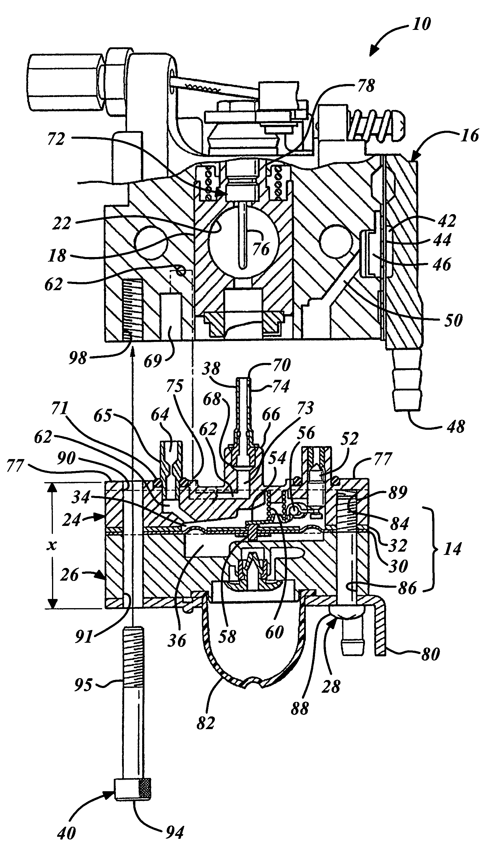
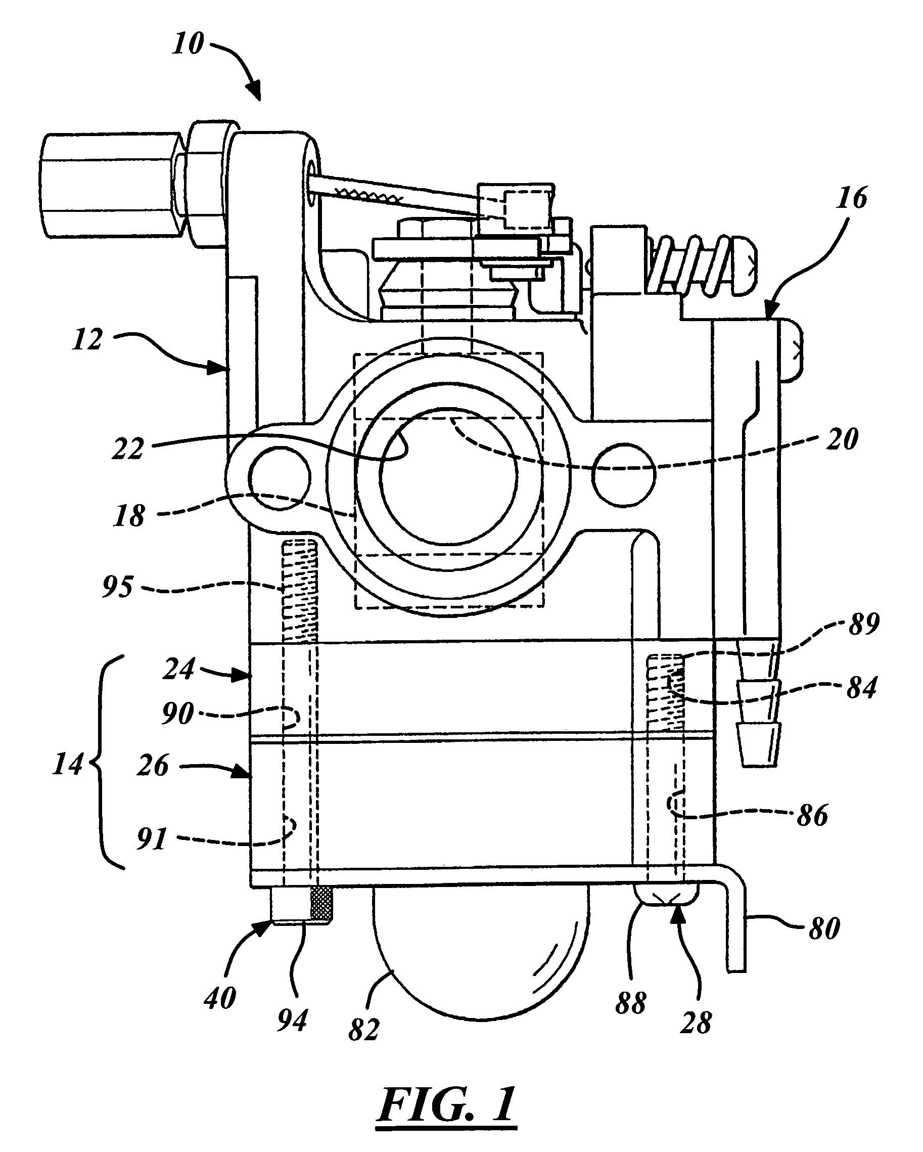
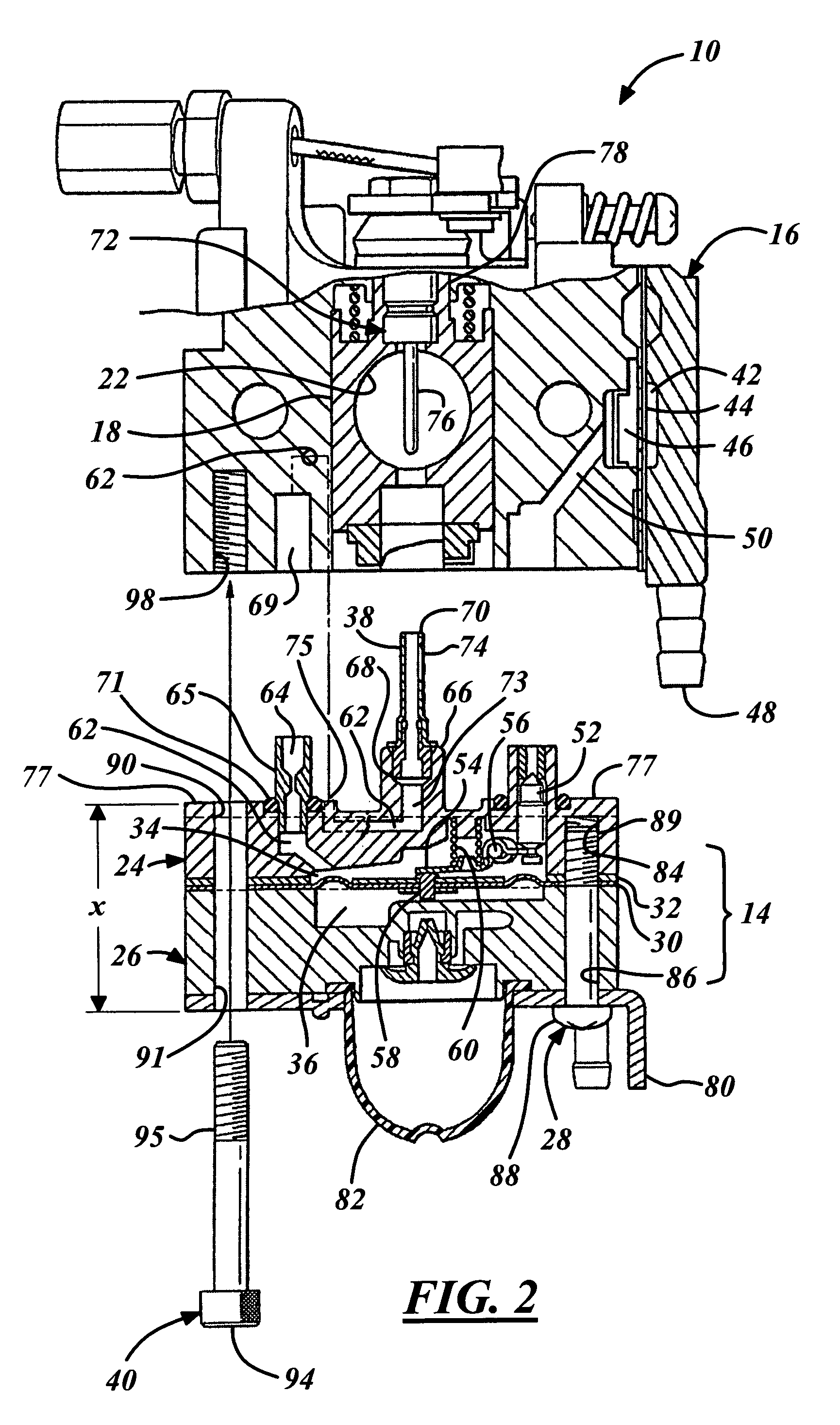
[0014]Referring in more detail to the drawings, FIG. 1 illustrates a carburetor 10 having a main body 12 with a fuel metering chamber assembly 14, according to one presently preferred embodiment, attached to an air-fuel mixing portion or main body 16. The air-fuel mixing body 16 has an air-fuel mixture passage 20, a throttle valve 18 adapted for rotation about an axis 21, represented here as a rotary throttle valve, with a transverse through bore 22, by way of example and without limitation, and received in the air-fuel mixing passage 20. The fuel metering chamber assembly 14 has a metering chamber plate or upper body 24 and an atmospheric chamber plate or lower body 26, attached to one another via at least one, and preferably a pair of fasteners such as machine screws 28. As shown in FIG. 2, a diaphragm 30 and preferably a gasket or seal 32 are received between the upper and lower bodies 24, 26, to provide a fuel control or metering chamber 34 and an atmospheric chamber 36 on oppos...


PUM

PropertyMeasurementUnit
lengthaaaaaaaaaa
diameteraaaaaaaaaa
flexibilityaaaaaaaaaa

Abstract

A diaphragm carburetor for an internal combustion engine and method of assembly includes attaching an air-fuel mixing body to a fuel metering chamber assembly independent from assembling the fuel metering chamber assembly. The fuel metering chamber assembly has an upper body and a lower body attached to one another by at least one fastener with a diaphragm carried therebetween. A fuel metering chamber is defined on one side of the diaphragm and an atmospheric chamber is defined on another side of the diaphragm. Another fastener attaches the fuel metering chamber assembly to the air-fuel mixing body independently from the fastener attaching the upper and lower bodies together. Accordingly, the fuel metering chamber assembly is removable from the air-fuel mixing body without removing the fastener attaching the upper and lower bodies to one another preferably for cleaning of a fuel nozzle that when assembled projects into an air-fuel mixing passage in the mixing body.

Description

REFERENCE TO RELATED APPLICATION[0001]Applicant claims priority of Japanese application, Ser. No. 2005-003355-filed Jan. 11, 2005.FIELD OF THE INVENTION[0002]The present invention relates generally to carburetors and more particularly to diaphragm carburetors and their method of assembly.BACKGROUND OF THE INVENTION[0003]For many decades small internal combustion engines, such as those used for motor vehicles, recreational vehicles and lawn and garden tools like chain saws, trimmers, tractors, and lawn mowers, have typically used diaphragm carburetors to regulate the air-fuel mixture supplied to the internal combustion engine. Typically diaphragm carburetors have a main body with an air-fuel mixing passage adapted for fluid communication with a fuel metering chamber assembly, which in turn is in fluid communication with a fuel pump chamber. The fuel metering chamber assembly is typically constructed from separate bodies attached to one another with a diaphragm carried between the sep...

Claims


Application Information

Patent Timeline
Patent Type & Authority Patents(United States)
IPC IPC(8): F02M17/04
CPCF02M17/04Y10T29/49963
Inventor TOBINAI, TERUHIKO
Owner WALBRO ENGINE MANAGEMENT
Features
  • R&D
  • Intellectual Property
  • Life Sciences
  • Materials
  • Tech Scout
  • Unparalleled Data Quality
  • Higher Quality Content
  • 60% Fewer Hallucinations
Learn More