Supercharge Your Innovation With Domain-Expert AI Agents!

Wave generator

a generator and wave technology, applied in the field of wave generators, can solve the problems of low yield ratio and high cost, and achieve the effect of clean water and clear water

Inactive Publication Date: 2008-05-20
TASI CHANG HUA
View PDF8 Cites 25 Cited by
  • Summary
  • Abstract
  • Description
  • Claims
  • Application Information

AI Technical Summary

Benefits of technology

"The present invention provides a wave generator that can produce clean and clear water. It includes a seat, a positioning ring, a wave generating unit, a flow-steady base, a flow-collecting mask, a positioning unit, a filtering web, a positioning rod, and an enlarged tapered head. The wave generating unit has a central platform with projecting blocks and flow channels for draining water. The positioning unit can accurately position the flow-steady base and the flow-collecting mask. The filtering web has holes formed as an umbrella shape and a positioning rod extending from the central lower side. The technical effects of this invention are that it can produce high-density water sprays and accumulate sand in the water, resulting in a cleaner and clearer water."

Problems solved by technology

This will induce low yield ratio and high cost.

Method used


Image

  • Wave generator
  • Wave generator
  • Wave generator

Examples


Embodiment Construction

[0013]In order that those skilled in the art can further understand the present invention, a description will be described in the following in details. However, these descriptions and the appended drawings are only used to cause those skilled in the art to understand the objects, features, and characteristics of the present invention, but not to be used to confine the scope and spirit of the present invention defined in the appended claims.

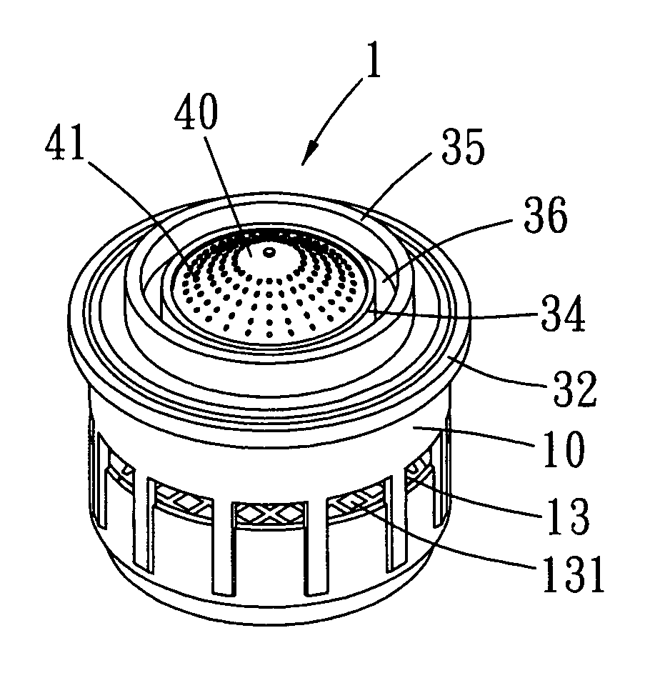
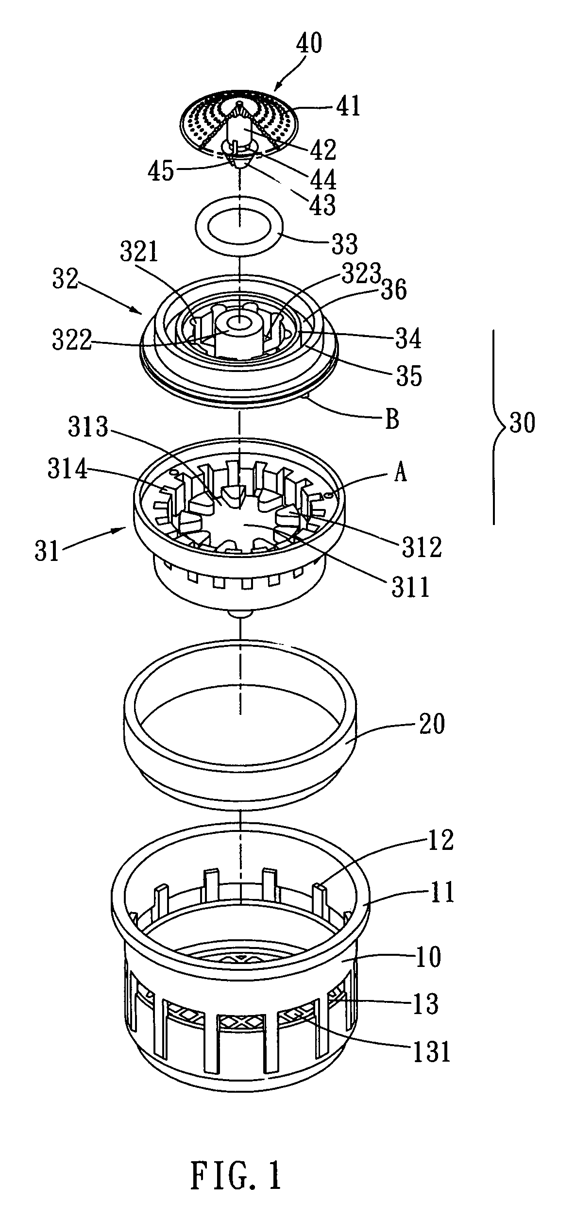
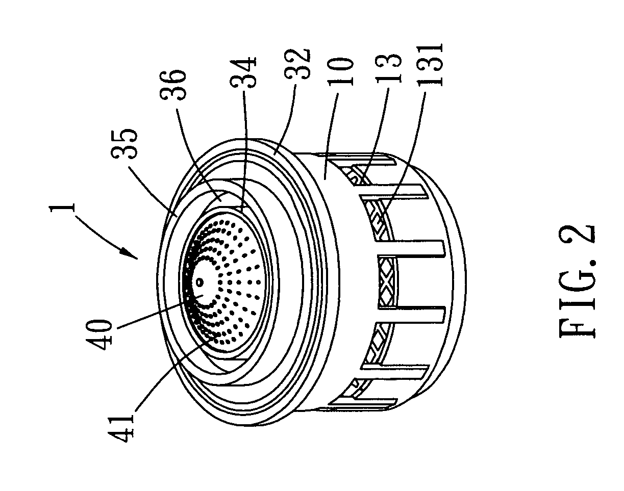
[0014]Referring to FIGS. 1 to 7, a wave generator used with a faucet according to the present invention is illustrated. The present invention has the following elements.

[0015]A seat 10 has an approximate U shape cross section. A top of the seat 10 is formed with a flange 11. An inner wall of the seat 10 is annularly arranged with a plurality of supporting blocks 12 which are spaced one by one. A bottom of the seat 10 is installed with a filter net 13. The filter net 13 has a plurality of net holes 131. Water flows through the net holes 131. The ne...


PUM

PropertyMeasurementUnit
T shapeaaaaaaaaaa
densityaaaaaaaaaa
shapesaaaaaaaaaa

Abstract

A wave generator comprises a seat; a positioning ring a wave generating unit received in an upper side of the seat; the wave generating unit being formed by a flow-steady base and a flow-collecting mask; the flow-steady base having a central platform; an upper surface of the central platform having a plurality of projecting blocks which are annularly arranged; the spaces between projecting blocks being formed as flow channels; an inner wall of the wave generating unit being formed with a plurality of longitudinal slots for draining water; a positioning unit for positioning the flow-steady base and the flow-collecting mask precisely; a filtering web having a plurality of holes which formed as an umbrella shape; a positioning rod extending from a central lower side of the web; and a front end of the positioning rod being formed an enlarged tapered head.

Description

FIELD OF THE INVENTION[0001]The present invention relates to wave generators, and in particular to a wave generator in that, water sprays out with a higher density and sands in the water can be accumulated in an annular groove so that the water is clean and clear.BACKGROUND OF THE INVENTION[0002]The prior art wave generator has some disadvantages which will be described herein. The water channels of the flow-steady base must be aligned to the slots of the flow-collecting mask so that water can flow out. However no positioning structure is formed so that water flows through the flow-steady base and flow-collecting mask are hindered by the blocks at the flow-steady base. Thus, the density of water flowing out from the faucet is not so high as expected. Therefore, in assembly, the worker must take time to align the flow-steady base and flow-collecting mask. This will induce low yield ratio and high cost.SUMMARY OF THE INVENTION[0003]Accordingly, the primary object of the present invent...

Claims


Application Information

Patent Timeline
Patent Type & Authority Patents(United States)
IPC IPC(8): E03C1/08
CPCE03C1/084E03C2201/40Y10S261/22
Inventor TASI, CHANG-HUA
Owner TASI CHANG HUA
Features
  • R&D
  • Intellectual Property
  • Life Sciences
  • Materials
  • Tech Scout
  • Unparalleled Data Quality
  • Higher Quality Content
  • 60% Fewer Hallucinations
Learn More