Filter and system for improved sealing on a vacuum cleaner

a vacuum cleaner and filter body technology, applied in the field of vacuum cleaners, can solve the problems of vacuum cleaners notoriously dusty and dirty, wear on the internal vacuum motor, impeller, etc., and achieve the effect of improving the sealing performance of the vacuum cleaner, reducing the risk of rust and dust, and reducing the service life of the vacuum cleaner

Active Publication Date: 2008-05-20
EMERSON ELECTRIC CO
View PDF10 Cites 46 Cited by
  • Summary
  • Abstract
  • Description
  • Claims
  • Application Information

AI Technical Summary

Benefits of technology

[0013]The disclosure provides a filter for mounting in a vacuum cleaner, such as a wet and dry vacuum cleaner, having a seal at generally each end, and a corresponding mounting structure that focuses compressive sealing forces on specific seal components rather than the filter body as a whole. The sealing is directed primarily to portions of the seals on the filter ends that are compressed or “pinched” between adjacent surfaces. The concentrated compressive stress provides a well-defined region to consistently provide a sealing engagement. The compressive force can thereby remain relatively constant through multiple uses of the filter.
[0016]The disclosure further provides a method of sealing a filter to a vacuum cleaner, the vacuum cleaner having a mounting assembly and a filter support assembly coupled to the mounting assembly to support the filter, the filter support assembly comprising a main filter support fixedly coupled to the mounting assembly and an outer filter support slidably coupled around a peripheral portion of the main filter support, comprising: stretching a lateral seal portion of the filter outwardly around the outer filter support and sliding the filter toward an end of the outer filter support to a smaller cross sectional portion formed between the outer filter support and the mounting assembly; allowing the lateral seal portion to at least partially resume an unstretched position in the smaller cross sectional portion thereby overlapping a portion of the outer filter support with the lateral seal portion; and compressing the overlapping portion to effect a seal of the filter to the vacuum cleaner while avoiding compressing or stretching a filter element of the filter coupled to the lateral seal portion.

Problems solved by technology

Vacuum cleaners are notoriously dusty and dirty, requiring some method to separate the dust and the dirt from the exhaust air.
Experience has shown that operators have difficulty determining how much compressive force to use on the filter body, because such installation includes compressing the filter element as well.
At times, operators use too little force and achieve an inadequate seal, thus allowing leakage of fine dust, resulting in wear on the internal vacuum motor, impeller, and other internal structures.
At other times, operators apply too much force and crush the filter or strip the attachment threads, causing repair or replacement of parts.

Method used


Image

  • Filter and system for improved sealing on a vacuum cleaner
  • Filter and system for improved sealing on a vacuum cleaner
  • Filter and system for improved sealing on a vacuum cleaner

Examples


Embodiment Construction

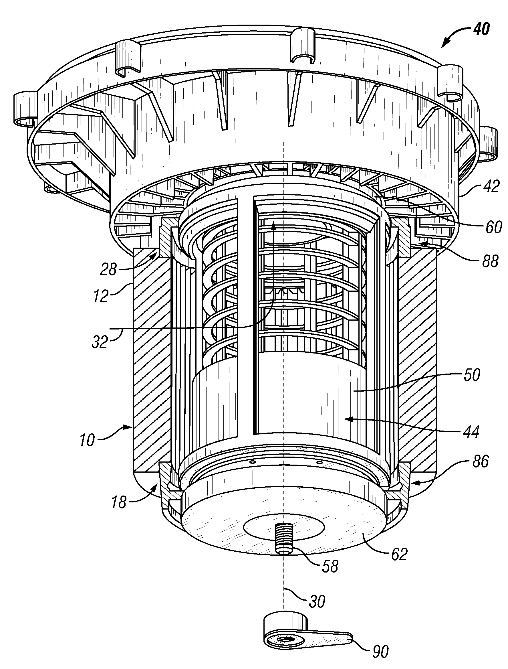
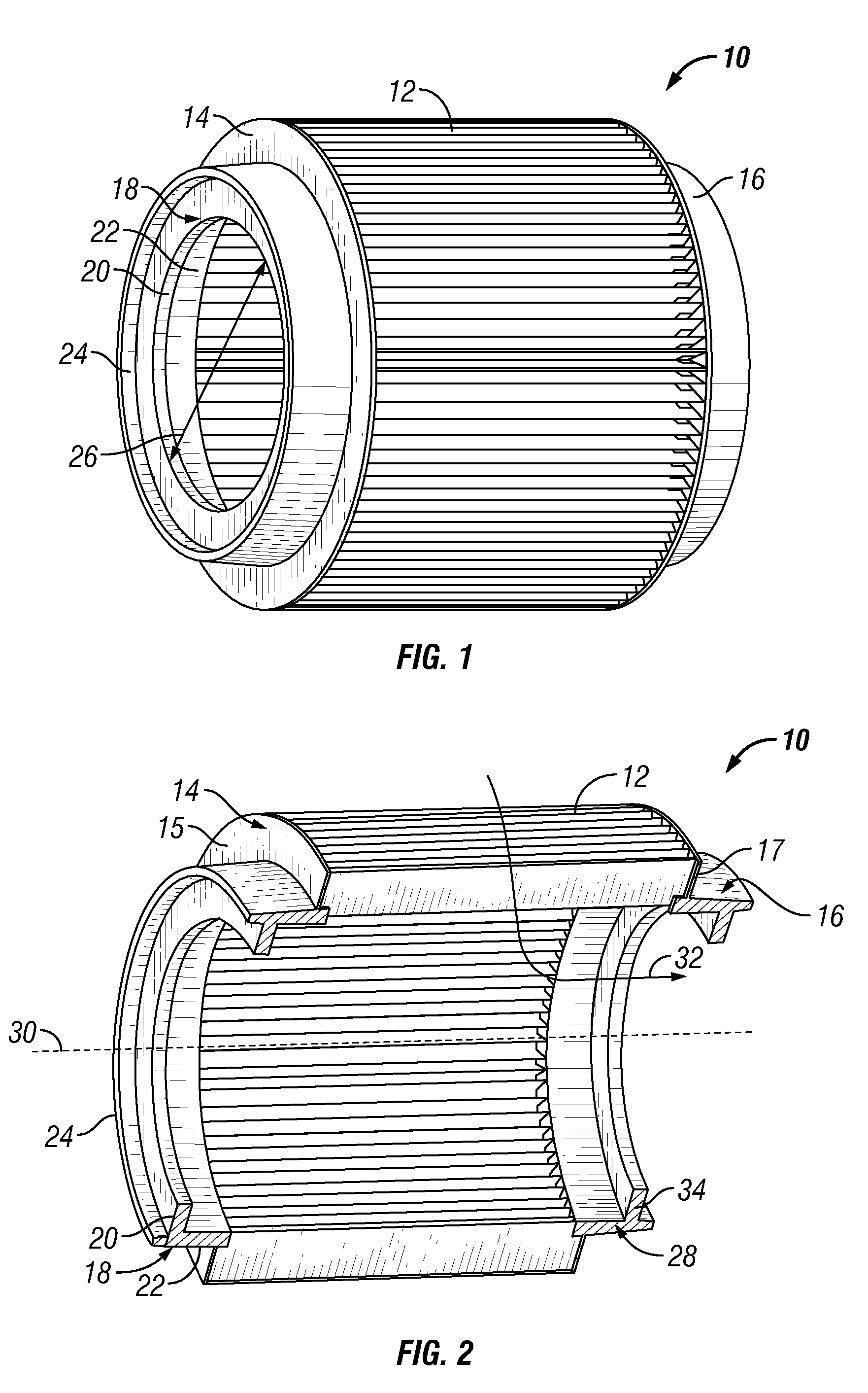
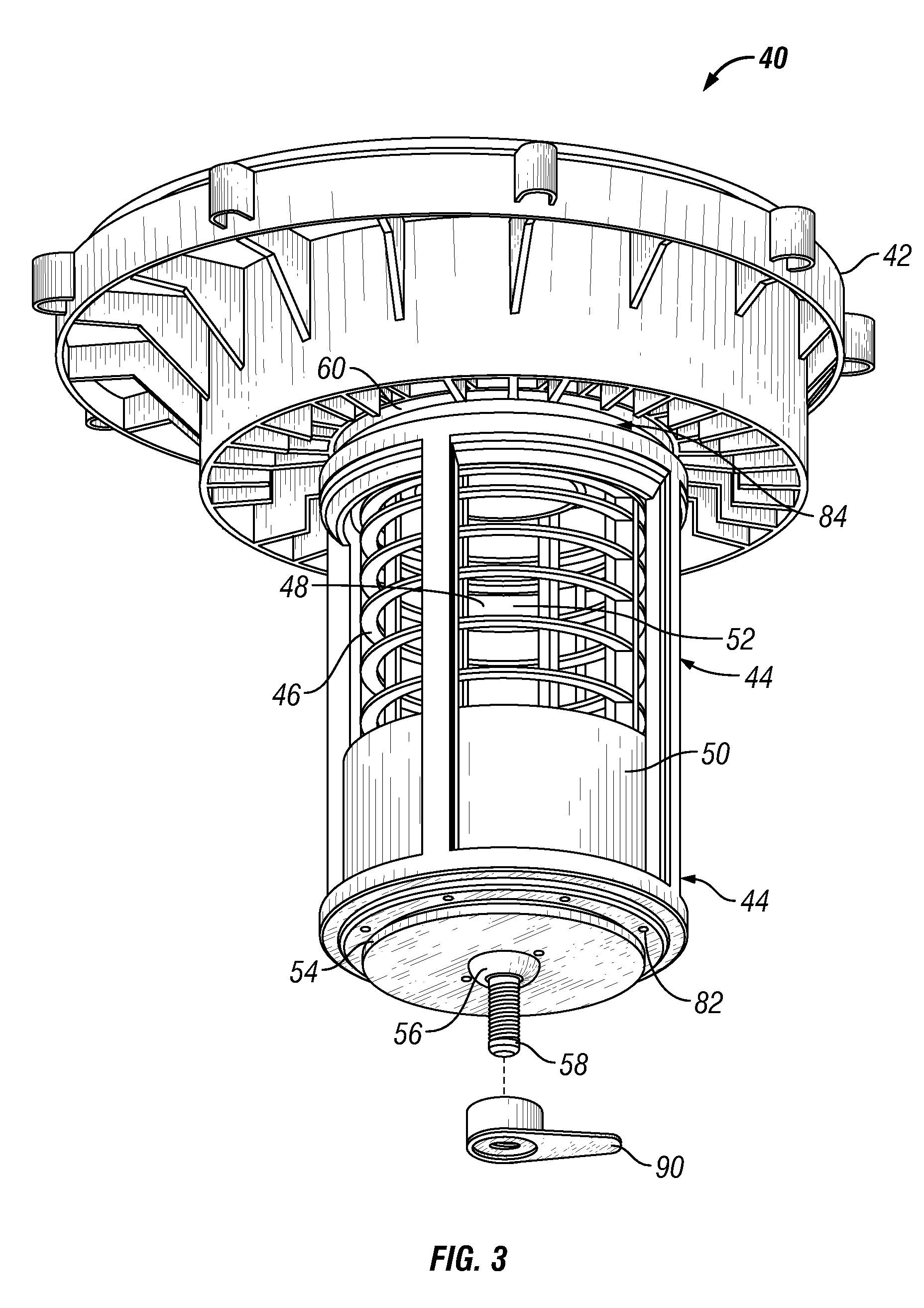
[0027]FIG. 1 is a perspective schematic view of an exemplary filter of the present disclosure. FIG. 2 is a perspective cut-away schematic view of the exemplary filter, showing the filter seals. The figures will be described in conjunction with each other. The filter 10 includes a first seal end 14, a filter element 12 coupled to the first end 14, and a second seal end 16 coupled to the filter element, the components being disposed along a longitudinal axis 30. The filter element is generally porous material, such as cloth or paper, and can be reinforced with metal or plastic mesh. The media flow 32, such as air, generally is from an outer peripheral portion of the filter 10 through the filter element 12 and into the inner spaces of the filter and then through a filter support assembly and the vacuum cleaner mounting assembly for exhausting, described in more detail below.

[0028]Generally, the filter ends 14, 16 include non-porous material to reduce leakage therethrough and seal at th...


PUM

PropertyMeasurementUnit
diameteraaaaaaaaaa
vacuumaaaaaaaaaa
surface areaaaaaaaaaaa

Abstract

The disclosure provides a filter for mounting in a vacuum cleaner, such as a wet and dry vacuum cleaner, having a seal at generally each end, and a corresponding mounting structure that focuses compressive sealing forces on specific seal components rather than the filter body as a whole. The sealing is directed primarily to portions of the seals on the filter ends that are compressed or “pinched” between adjacent surfaces. The concentrated compressive stress provides a well-defined region to consistently provide a sealing engagement. The compressive force can thereby remain relatively constant through multiple uses of the filter.

Description

CROSS REFERENCE TO RELATED APPLICATIONS[0001]This application claims the benefit of U.S. Provisional Appl. No. 60 / 739,510, filed Nov. 23, 2005, the contents of which are hereby incorporated by reference.STATEMENT REGARDING FEDERALLY SPONSORED RESEARCH OR DEVELOPMENT[0002]Not applicable.REFERENCE TO APPENDIX[0003]Not applicable.BACKGROUND OF THE INVENTION[0004]1. Field of the Invention[0005]The disclosure relates to the field of vacuum cleaners. More specifically, the disclosure relates to vacuum cleaners having removable filters.[0006]2. Description of the Related Art[0007]Vacuum cleaners are notoriously dusty and dirty, requiring some method to separate the dust and the dirt from the exhaust air. Hence, filters are commonly used to perform this separation function. There often is a need to remove and re-attach the filter, for example when cleaning the filter or replacing it with a new filter. With the type of vacuum cleaner known as wet and dry vacuum cleaners, the filter is also o...

Claims


Application Information

Patent Timeline
Patent Type & Authority Patents(United States)
IPC IPC(8): B01D39/00
CPCA47L9/127B01D46/0005B01D46/2411B01D2265/025B01D2279/55
Inventor GIERER, JOSEPH T.
Owner EMERSON ELECTRIC CO
Why Eureka
Try Eureka