Co-cured resin transfer molding manufacturing method

a technology of transfer molding and resin, which is applied in the field of composite construction, can solve the problems of wasting considerable time and money in constructing stiffened composite structures, and achieve the effects of reducing or eliminating touch labor, and reducing the weight of stiffened composite structures

Active Publication Date: 2008-05-20
NORTHROP GRUMMAN SYST CORP
View PDF34 Cites 1 Cited by
  • Summary
  • Abstract
  • Description
  • Claims
  • Application Information

AI Technical Summary

Benefits of technology

[0004]Embodiments of the invention provide a number of technical advantages. Embodiments of the invention may include all, some, or none of these advantages. A composite structure manufactured according to one embodiment of the present invention is cost-efficient because of the substantial reduction or elimination of touch labor allowed by part count and fastener count reduction due to part integration. In addition, superior dimensional control and less weight of stiffened composite structures is achieved. This weight reduction is particularly advantageous in aircraft applications. A manufacturer of composite structures may tailor a skin panel for weight efficiency and high performance via unidirectional prepreg product forms, for example. In some embodiments, no mechanical fasteners or adhesives are needed to attach the substructure to the skin panel, which saves considerable time and money in constructing stiffened composite structures. However, Z-pins film or adhesives may be used to complement the co-curing of the substructure to the skin panel to create crack propagation resistance.

Problems solved by technology

In some embodiments, no mechanical fasteners or adhesives are needed to attach the substructure to the skin panel, which saves considerable time and money in constructing stiffened composite structures.

Method used


Image

  • Co-cured resin transfer molding manufacturing method
  • Co-cured resin transfer molding manufacturing method
  • Co-cured resin transfer molding manufacturing method

Examples


Embodiment Construction

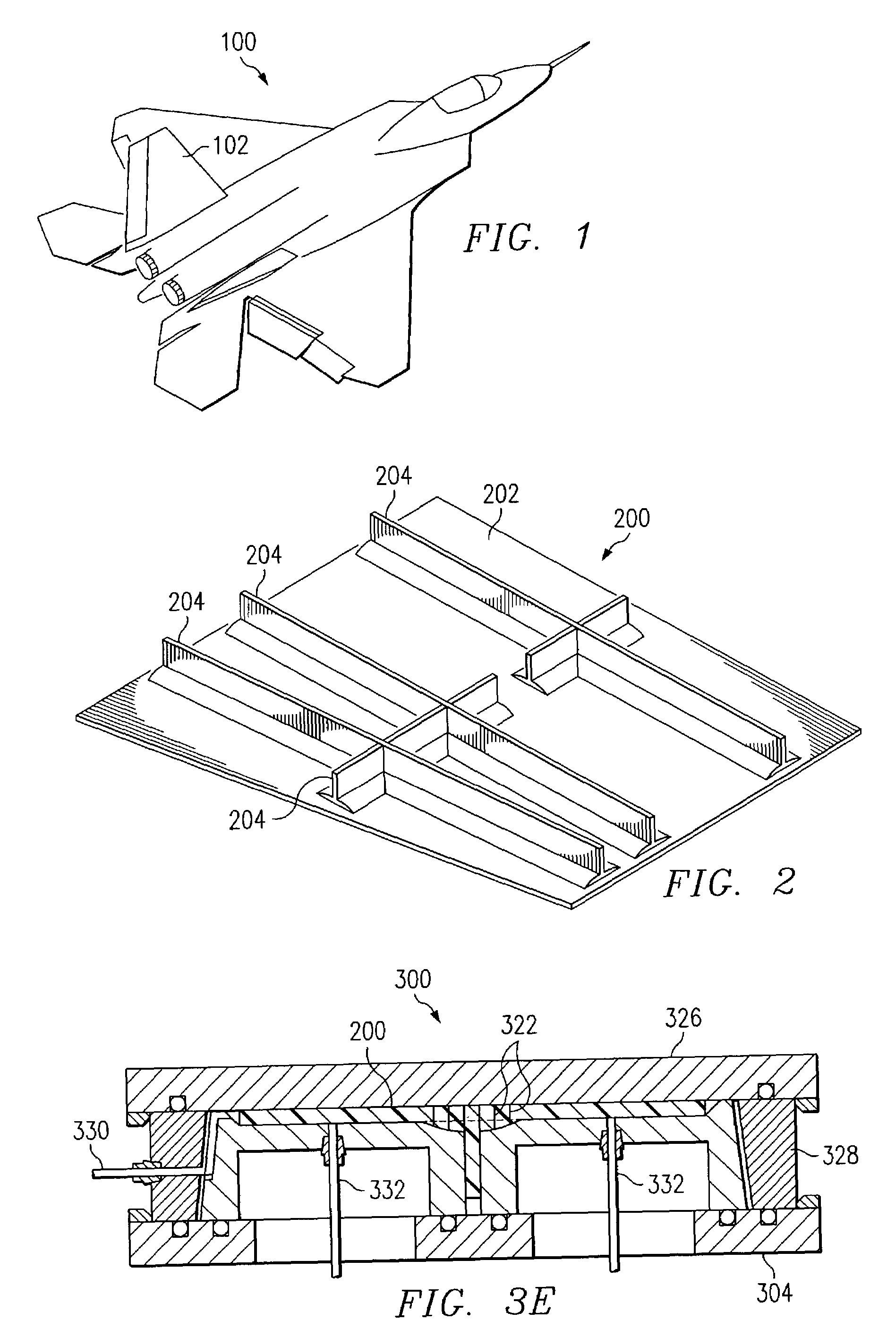
[0011]Example embodiments of the present invention and their advantages are best understood by referring now to FIGS. 1 through 3E of the drawings, in which like numerals refer to like parts.

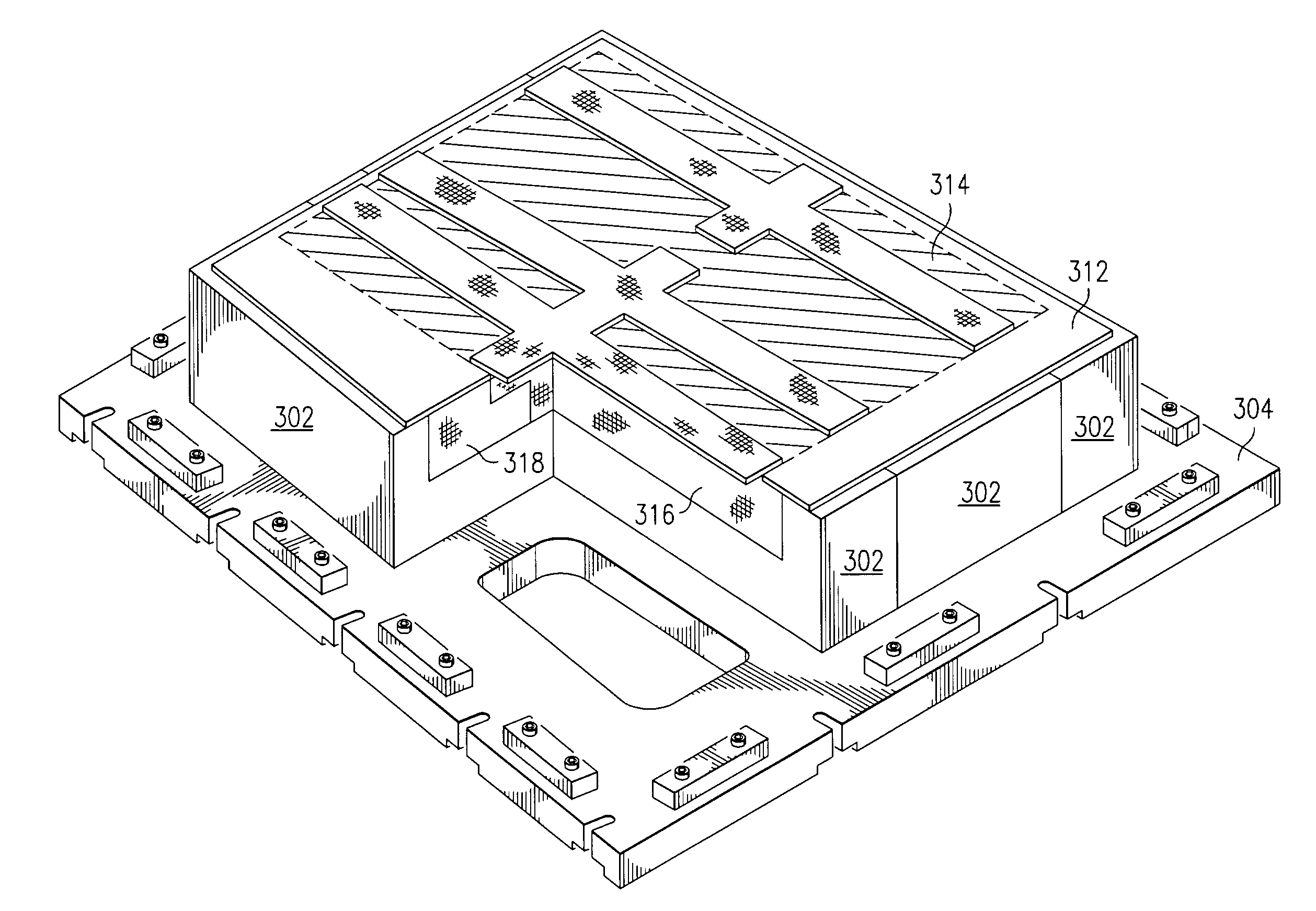
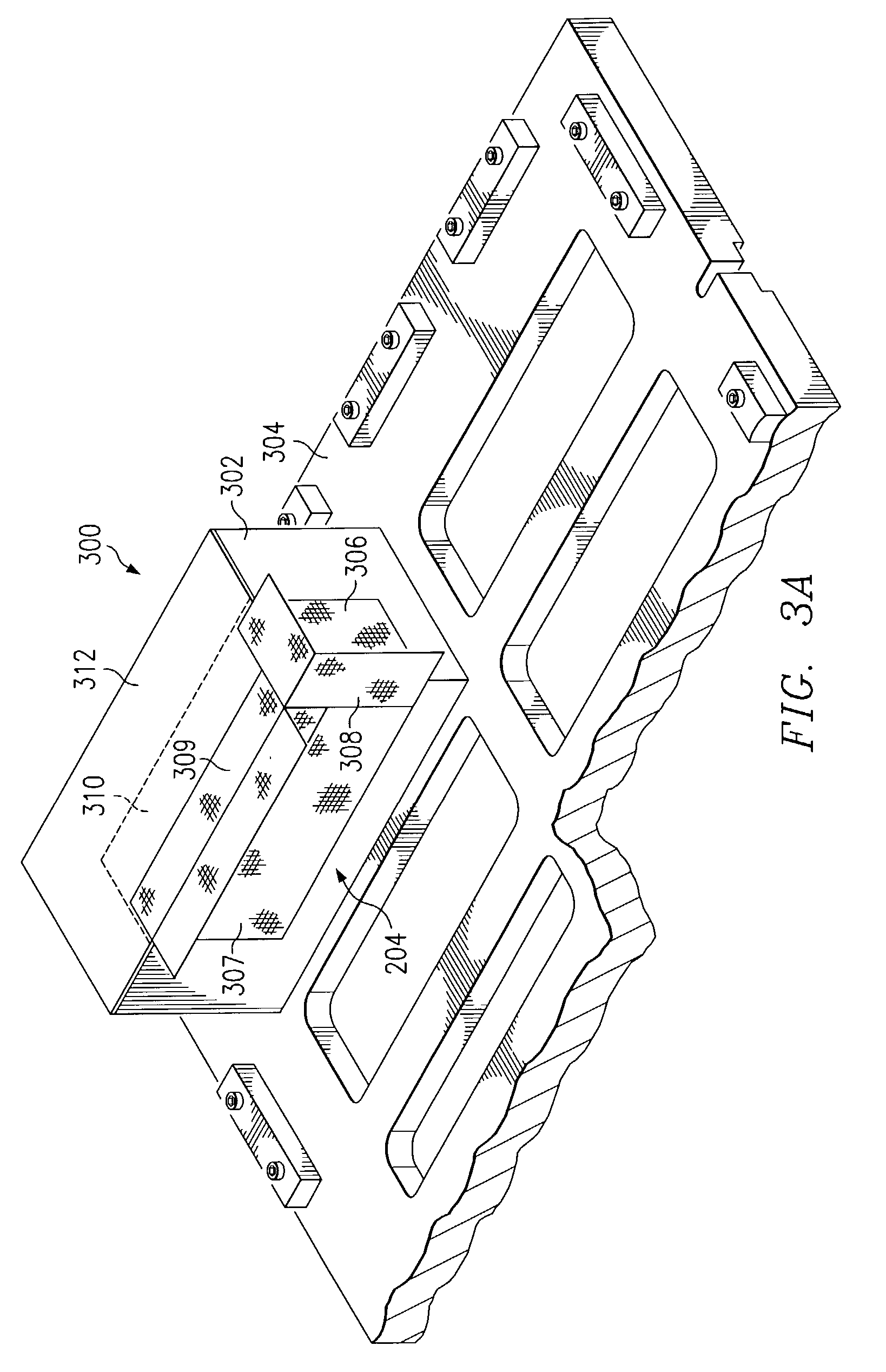
[0012]FIG. 1 is a perspective view of an aircraft 100 having a panel 102 formed from a composite structure 200 (FIG. 2) constructed according to one embodiment of the present invention. Aircraft 100 may be any suitable aircraft and panel 102 may be any suitable structural panel on aircraft 100, such as a tail panel, a wing panel, or a fuselage panel. Although aircraft 100 is illustrated in FIG. 1, panel 102 may be employed in any suitable aircraft, space, land / sea vehicle, or other machines, devices, or structures formed by composite materials. The following detailed description uses an aircraft application to illustrate one or more embodiments of composite structure 200 manufactured according to the teachings of the present invention. One embodiment of composite structure 200 is illustrated bel...


PUM

PropertyMeasurementUnit
temperatureaaaaaaaaaa
pressureaaaaaaaaaa
temperatureaaaaaaaaaa

Abstract

According to one embodiment of the invention, a co-cured resin transfer molding manufacturing method includes providing a tool having one or more tooling details and disposing one or more preforms proximate the one or more tooling details. The one or more preforms are either dry or binderized. The method further includes disposing a high permeability medium outwardly from the one or more tooling details, disposing a prepreg skin panel outwardly from the high permeability medium, disposing the one or more tooling details and the prepreg skin panel within the tool, injecting a resin into the one or more preforms, and curing the one or more preforms and the prepreg skin panel.

Description

TECHINICAL FIELD OF THE INVENTION[0001]The present invention relates generally to the field of composites construction and, more particularly, to a co-cured resin transfer molding manufacturing method.BACKGROUND OF THE INVENTION[0002]Composite structures are desirable in many industries for many applications. For example, aircraft, space, and land / sea vehicles employ a variety of curved and multiple-contoured surface structures in their fabrication. Composite materials are commonly used for these structures because, among other desirable attributes, composite materials have high strength-to-weight ratios and allow the design and fabrication of large integrated composite structures. Even so, structures formed from composite materials oftentimes need to be stiffened or joined to adjacent structures. Therefore, manufacturers of composite structures are continually searching for better and more economical ways of stiffening and / or assembling composite structures.SUMMARY OF THE INVENTION...

Claims


Application Information

Patent Timeline
Patent Type & Authority Patents(United States)
IPC IPC(8): B29C45/16B29C70/44B29C70/48B29D99/00
CPCB29C70/443B29C70/48B29D99/0014B29D99/0028B29L2031/3076
Inventor HUSMANN, CHRISTOPHER H.SHEU, CHI H.SHIMAZU, DENISE M.
Owner NORTHROP GRUMMAN SYST CORP
Why Eureka
Try Eureka