Process for the synthesis of ammonia with low emissions of co2in atmosphere

a technology of ammonia and co2 in the atmosphere, which is applied in the field can solve the problems of increasing co2 flue emissions, increasing energy consumption, and less efficiency of ammonia synthesis plants, and achieves the effects of reducing co2 emissions, reducing co2 emissions, and increasing steam

Active Publication Date: 2020-02-20
CASALE SA
View PDF0 Cites 10 Cited by
  • Summary
  • Abstract
  • Description
  • Claims
  • Application Information

AI Technical Summary

Benefits of technology

[0111]Another advantage of the invention is that the greater flowrate of gas in the front end allows more heat to be recovered and more steam to be generated. The greater quantity of steam produced in the front end limits the duty of the respective auxiliary steam-generating apparatus; an advantage is that the fuel consumption (and potential source of CO2 emissions) is represented only by the primary reformer or fired heater. If the fuel of the reformer is replaced with synthesis gas (and if necessary the associated burners replaced) a substantial elimination or zeroing of the CO2 emissions is obtained.
[0112]Another advantage is that the invention does not require necessarily separation of hydrogen from the CO2-depleted syngas, i.e. purification of the CO2-depleted syngas into a gas which is rich in H2 and a waste gas, in order to obtain low CO2 emissions into the atmosphere. The CO2-depleted syngas may be used directly for ammonia synthesis after possible methanation.
[0113]In some embodiments it may be advantageous to perform a syngas gas purification in order to reduce the overall energy consumption of the process.
[0121]the process does not require intense purification of the synthesis gas in order to remove the inert components, it being sufficient to use the methanator (often the existing one); in particular, it is not necessary to perform any separation of the synthesis gas into an H2 and waste gas flow.
[0122]FIG. 1 shows a first embodiment of the invention.
[0123]FIG. 2 shows a second embodiment.

Problems solved by technology

The problem affects in particular the older ammonia plants which are less efficient than the new ones and have greater CO2 flue emissions in relation to the quantity of ammonia produced.
The associated plants are, however, costly and complicated, have a high energy consumption and require expensive solvent.
Therefore these CO2 capturing processes cannot be applied to the plants considered here since they would increase excessively the costs for production of the ammonia.
However, said purge flow accounts for a small amount of the total fuel and does not solve the problem of the CO2 emissions in the atmosphere.

Method used


Image

  • Process for the synthesis of ammonia with low emissions of co2in atmosphere
  • Process for the synthesis of ammonia with low emissions of co2in atmosphere
  • Process for the synthesis of ammonia with low emissions of co2in atmosphere

Examples


example

[0150]The following Table 1 refers to a plant with a capacity of 3000 metric tonnes per day (MTD) of ammonia produced.

[0151]Table 1 compares the following options:

(1) Plant of the prior art with primary reformer and air-fed secondary reformer.

(2) Plant of the prior art, as per option (1), with capturing of the CO2 from the fumes of the primary reformer.

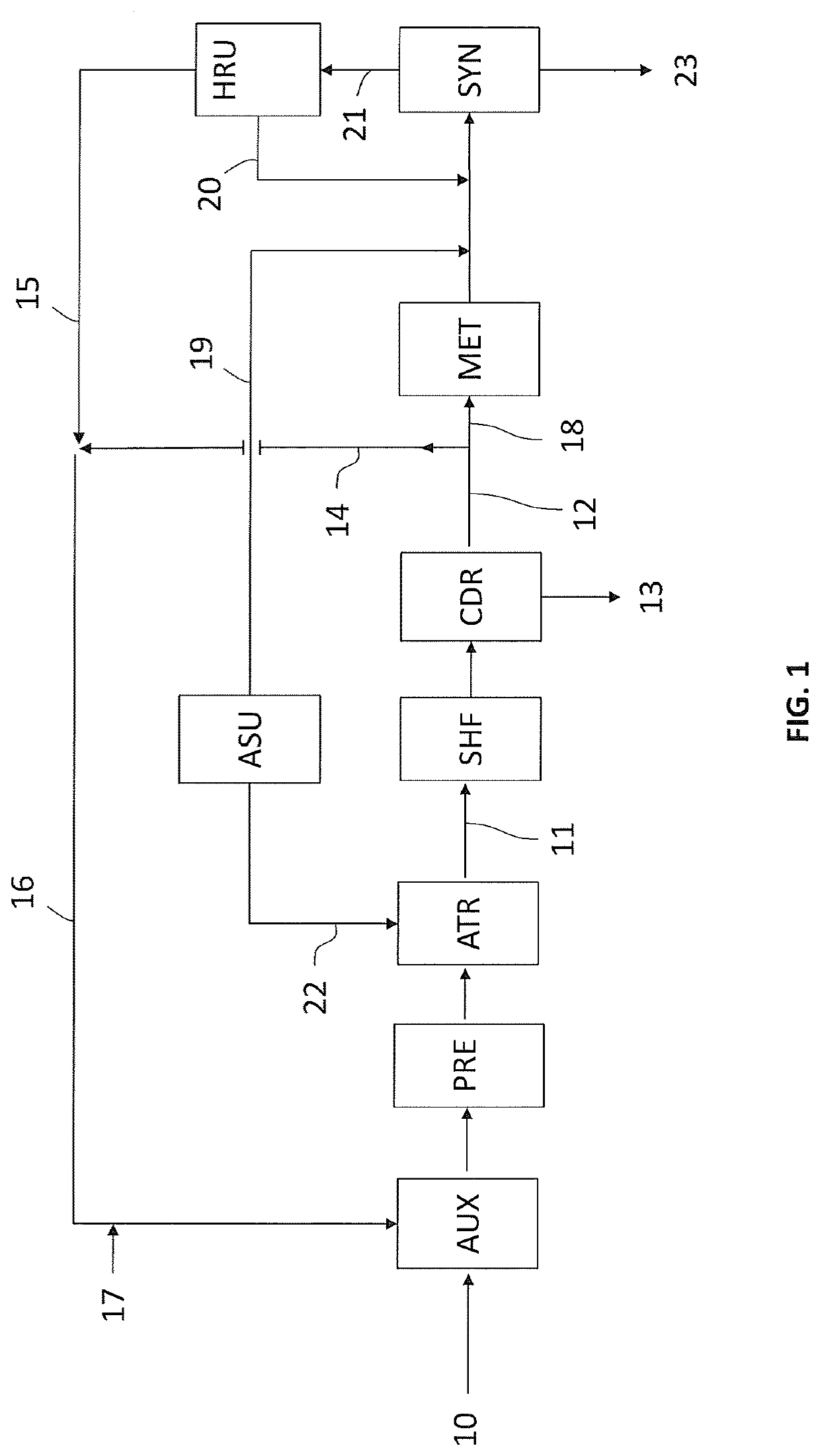
(3) Plant according to the invention, as per FIG. 1.

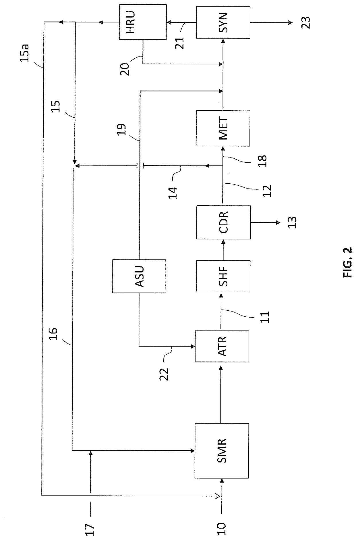
(4) Plant according to the invention, as per FIG. 2.

TABLE 1Option(1)(2)(3)(4)Prior artPrior artInv.Inv.NH3 productionMTD3000300030003000Net Natural Gas consumption based on gas LHVGcal / t NH36.77.47.06.9(FEED + FUEL-Steam exported e.g. to urea)Gcal / t NH3+0.7+0.3+0.2CO2 captured in processMTD3600360052005100CO2 to atmosphere (contained in flue gas)MTD2100200200200CO2 to atmosphere (contained in flue gas)t / t NH30.70.10.10.1Main Equipment sizeTotal fired heater duty%10012075105(reformer / fired heater + auxiliary boiler)Process CO2 removal capacity%100100145140ASU O2 capacity%n / an / a10060Fl...


PUM

PropertyMeasurementUnit
temperatureaaaaaaaaaa

Abstract

Process for the synthesis of ammonia from natural gas comprising conversion of a charge of desulphurized natural gas and steam, with oxygen-enriched air or oxygen, into a synthesis gas, and treatment of the synthesis gas with shift reaction and decarbonation, wherein a part of the CO2-depleted synthesis gas, obtained after decarbonation, is separated and used as fuel fraction for one or more furnaces of the conversion section, and the remaining part of the gas is used to produce ammonia.

Description

FIELD OF APPLICATION[0001]The invention relates to the field of ammonia synthesis plants fed with natural gas (NG).PRIOR ART[0002]The ammonia synthesis plants of the type considered here comprise a section adapted to convert the natural gas into a make-up gas containing hydrogen and nitrogen, and a synthesis section wherein said make-up gas reacts catalytically at high pressure to produce ammonia.[0003]The section which generates said make-up gas is referred to in the technical language as the “front end”. The term “back end” is instead used to denote the section for ammonia synthesis and the respective cooling section intended to cool the effluent of the synthesis section in order to separate the ammonia.[0004]In the front end, the desulphurized natural gas undergoes reforming, resulting in a gas containing essentially hydrogen, carbon monoxide CO and carbon dioxide CO2. Said gas then undergoes a shift reaction which converts CO into CO2; removal of CO2 (decarbonation) and preferab...

Claims


Application Information

Patent Timeline
Patent Type & Authority Applications(United States)
IPC IPC(8): C01C1/04C01B3/02C01B3/48
CPCC01C1/04C01B3/025C01B2203/0475C01B2203/0283C01B3/48C01B2203/0445C01B2203/068C01B2203/1241C01B2203/042C01B2203/0244C01B3/382C01B2203/043C01B3/36C01B2203/0255C01B2203/0415C01B2203/046C01B2203/0827C01B2203/143C01B2203/86Y02P30/00
Inventor BARATTO, FRANCESCOOSTUNI, RAFFAELE
Owner CASALE SA
Why Eureka
Try Eureka