
Concept for Reducing Crosstalk
a crosstalk and concept technology, applied in the field of crosstalk reduction concepts, can solve the problems of deteriorating the data reception on the second line, increasing the limiting factor of crosstalk, and reducing the signal-to-noise power ratio of bitlines, so as to achieve low loss of speed or performance
- Summary
- Abstract
- Description
- Claims
- Application Information
AI Technical Summary
Benefits of technology
Problems solved by technology
Method used
Image

Examples
Embodiment Construction
[0034]With regard to the following specification it should be noted that in the different embodiments the same or seemingly the same functional elements have the same reference numerals, and thus the description of these functional elements is interchangeable in the different embodiments which are illustrated in the following.
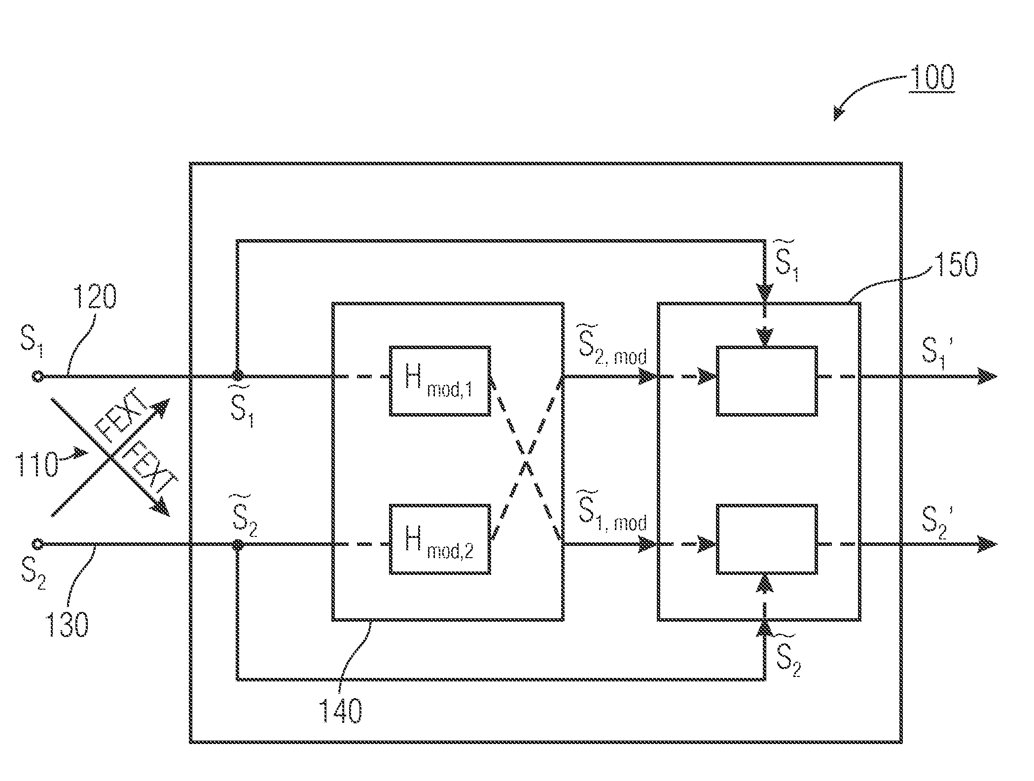
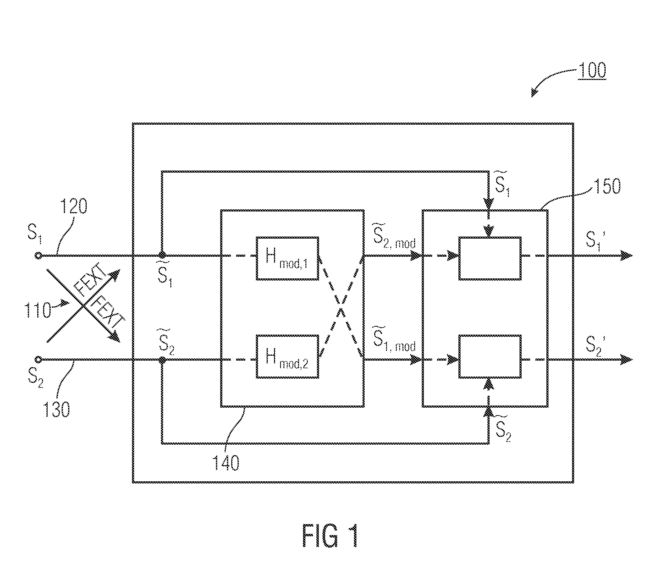
[0035]FIG. 1 shows a device 100 for reducing mutual crosstalk 110 of a first signal s1 routed across a first line 120 and a second signal s2 routed across a second line 130, wherein due to the mutual crosstalk 110 a first interfered signal {tilde over (s)}1 may be obtained at an output of the first line 120, and wherein a second interfered signal {tilde over (s)}2 may be obtained at an output of the second line 130.
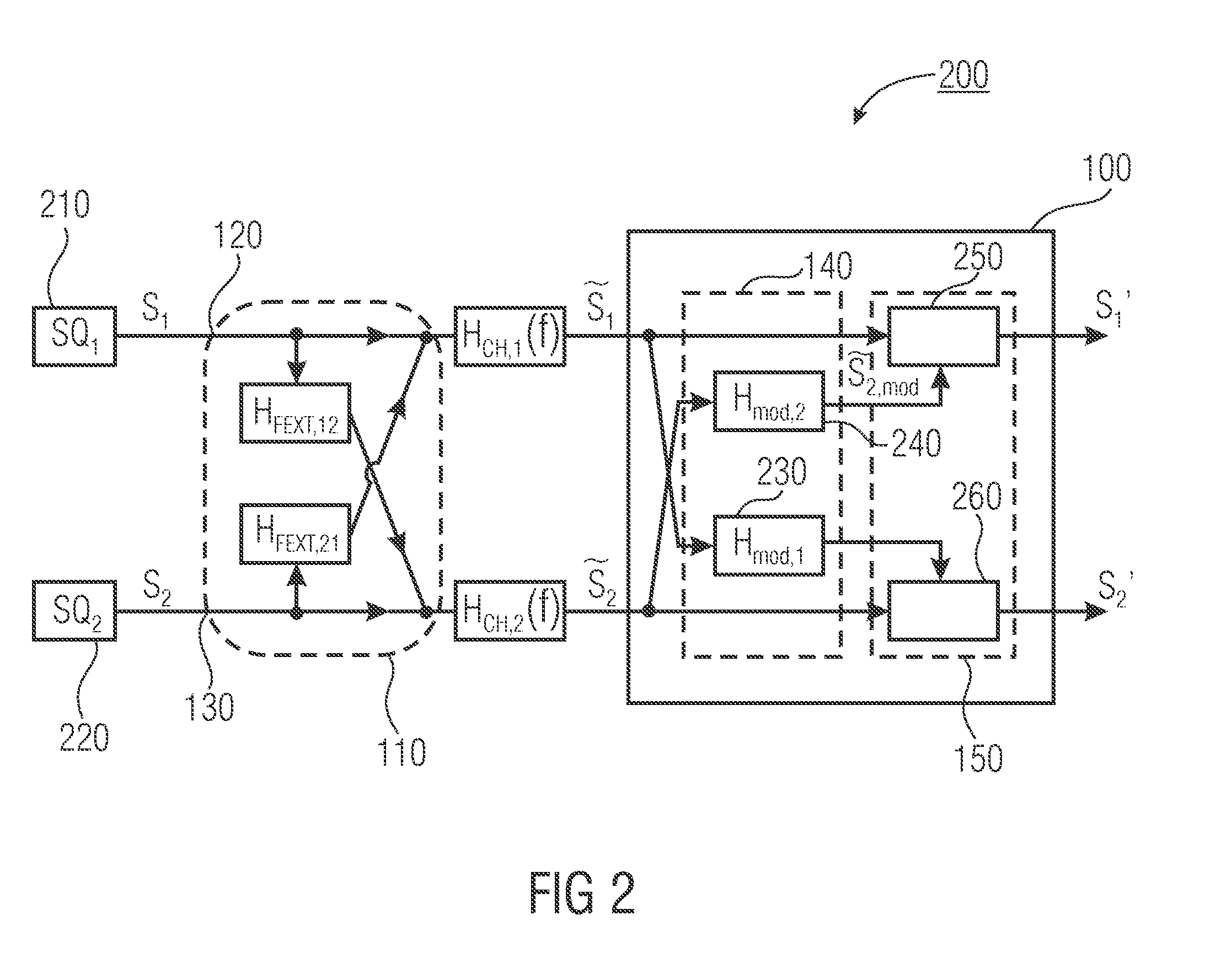
[0036]The device 100 includes a modifier 140 for modifying the first interfered signal {tilde over (s)}1, interfered by crosstalk due to the second signal s2, and for modifying the second interfered signal {tilde over (s)}2, interfered by crosstalk d...
PUM
 Abstract
Description
Claims
Application Information