
Method and device for determining a characteristic value that is representative of the condition of a gas

a technology of characteristic value and flow, which is applied in the direction of specific gravity measurement, material heat development, instruments, etc., can solve the problems of inability to accurately control the mass flow of control devices, and the nature of flowing substances, so as to achieve accurate and reproducible temperature difference measurement and reliable characterisation

Inactive Publication Date: 2008-05-27
EMERSON ELECTRIC CO
View PDF13 Cites 15 Cited by
  • Summary
  • Abstract
  • Description
  • Claims
  • Application Information

AI Technical Summary

Benefits of technology

The invention provides a device and method for accurately and reliably characterizing a flowing substance, gas or liquid, using a simple and compact device. The device includes a transport duct, heating or cooling element, temperature difference sensor, flow control means, and evaluation means. The method involves heating or cooling the substance, measuring the temperature difference, controlling the flow, and comparing the temperature difference with calibration substances. The invention allows for accurate and reproducible temperature difference measurement, which is important for reliable characterization of the flowing substance.

Problems solved by technology

However, there are also situations where the nature of the flowing substance is not known and can vary in time.
In such a situation, most flow control devices, like thermal flow controllers, cannot deliver an accurately controlled mass flow.
Because of these unknown changes in the mass flow and heat of combustion, problems can occur like the incomplete combustion of the gas, a too low energy recovery and emission problems.
Well known devices for the combustionless characterisation of flowing substances, like chromatography or spectrometry, are accurate but have the disadvantages that they are difficult to integrate in-line, that the response time for characterisation of the substance is still too long for accurate control of the flow and that the devices are too expensive and too big for many applications.
Because this calorimeter requires two flow meters it is rather complex, expensive and bulky.
Further, the accuracy and reliability are insufficient.
The problem of the described devices is that they are all relatively complex, expensive and bulky.
In particular, it is a disadvantage that the devices are deigned only for the evaluation of heat of combustion of a fuel gas.
More importantly, the devices are often too inaccurate and lack reproducibility for more demanding applications.

Method used


Image

  • Method and device for determining a characteristic value that is representative of the condition of a gas
  • Method and device for determining a characteristic value that is representative of the condition of a gas
  • Method and device for determining a characteristic value that is representative of the condition of a gas

Examples


Embodiment Construction

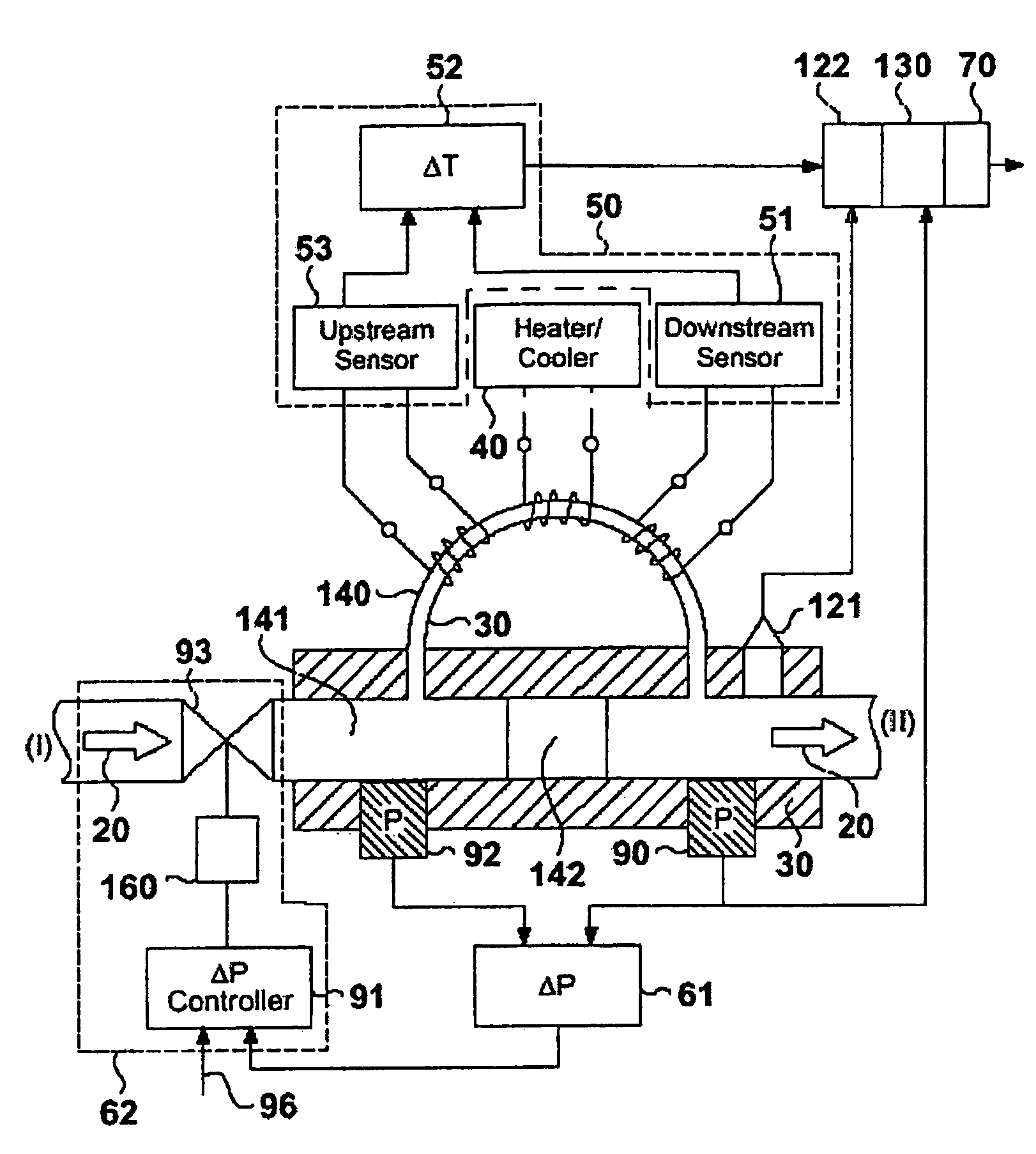
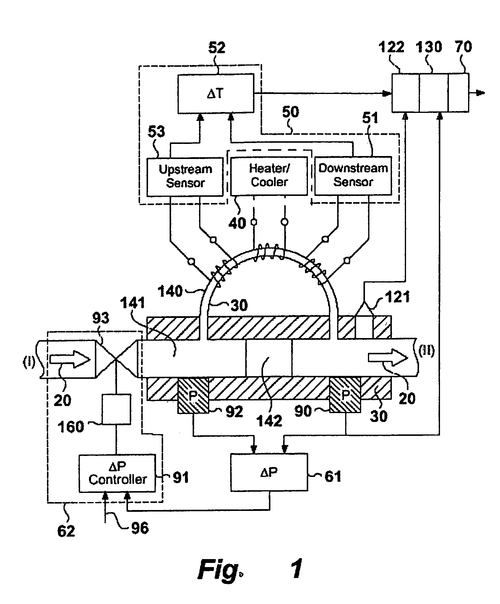
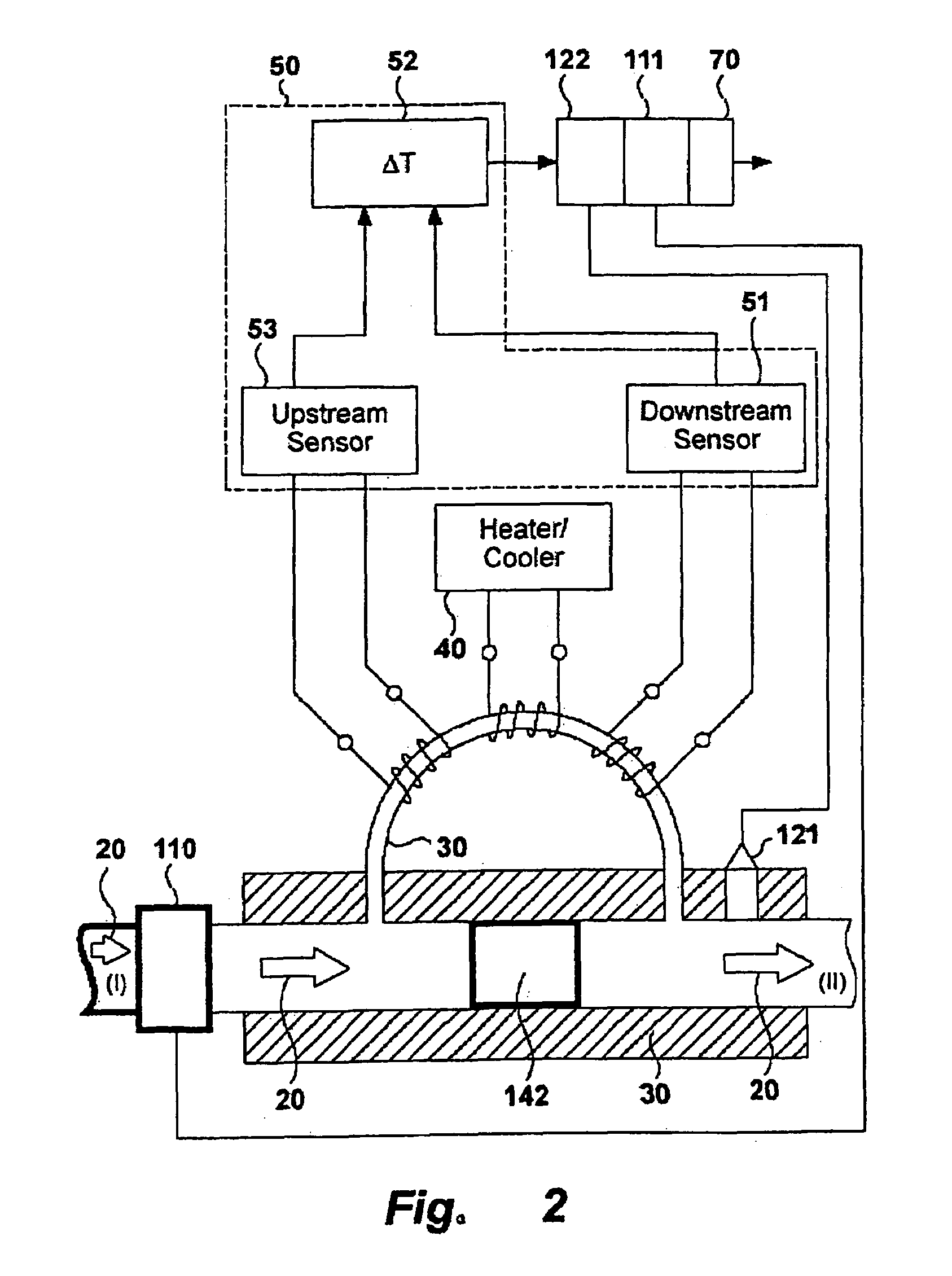
[0029]The flowing substance is forced to flow through a transport duct (30) on which is mounted a heating or a cooling element (40). The stream before that element is referred to as upstream (indicated I in FIGS. 1 and 2), the stream after the element is referred to as downstream (indicated II in FIGS. 1 and 2). In FIGS. 1 and 2 the flow is forced through the transport duct by a restrictor (142), which can be solid semi-permeable or variable. The heating or cooling element locally heats or cools the substance flowing through a transport duct with an accurately constant amount of heat creating a temperature difference in the flowing substance upstream and downstream of the heating or cooling element. The temperature difference sensor (50) comprises a first temperature measurement cell (51) downstream of the heating or cooling element. A single downstream measurement cell can be used if the temperature upstream is known from another source and available to the means (52) to determine ...


PUM

PropertyMeasurementUnit
temperatureaaaaaaaaaa
mass flowaaaaaaaaaa
flow rateaaaaaaaaaa

Abstract

The invention relates to a device and methods for characterizating flowing substances, liquid or gas. The device includes: a transport duct with a heating or a cooling element; a temperature difference sensor having a temperature measurement cell downstream of the heating or cooling element and means to determine a temperature difference in the flowing substance upstream and downstream of the heating or cooling element; a flow control means having flow measurement means for measuring a mass flow characteristic and a flow correction means for correcting for measured mass flow variations; and an evaluation means for evaluating a characterizing feature of the flowing substance comprising a function relating temperature differences measured on one or more calibration substances to one or more characterizing features of the flowing substance. Various embodiments relate to the related use and methods of the device for identification and control of the flowing substance.

Description

[0001]This application is a 35 U.S.C. §371 application of WO 2004 / 036209, filed Oct. 17, 2003 claiming priority to EP Appl. No. 02023415.9 filed Oct. 18, 2002, both of which are incorporated herein by reference in their entirety.BACKGROUND OF THE INVENTION[0002]The invention relates to a device and methods for the characterisation of a flowing substance. Particular embodiments of the invention relate to the use of the device for the identification of a flowing substance, for controlling the flow of a fuel or combustion gas to deliver a controlled heat of combustion and for measuring the heat capacity of a gas. Further embodiments of the invention relate to a flow control device for controlling the flow rate of a flowing substance and a method for the combustion of a fuel or combustion gas.[0003]Flow control devices are used to deliver a controlled amount of a flowing substance. This works well in most situations, where the nature of a flowing substance is known and substantially con...

Claims


Application Information

Patent Timeline
Patent Type & Authority Patents(United States)
IPC IPC(8): G01N25/00G01F1/68G01F1/684G01N25/20G01N33/22
CPCG01F1/6847G01N25/005G01N33/225
Inventor BREKELMANS, KEES C. J. M. N.RIJSWIJK, JAN WILLEM J. W. VAN
Owner EMERSON ELECTRIC CO
Learn More