Detachable crawler
a technology of crawler and rubber belt, which is applied in the field of crawler, can solve the problems of large creaking noise of iron crawler, damage to road surface, driver's fatigue, etc., and achieve the effect of improving durability and increasing durability of rubber belt parts
- Summary
- Abstract
- Description
- Claims
- Application Information
AI Technical Summary
Benefits of technology
Problems solved by technology
Method used
Image
Examples
first embodiment
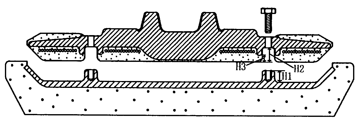
[0052]Next, an alternate example of the concave part 10 and the protrusion 7 for fitting the rubber pad 5 to the rubber belt part 4 in the first embodiment will be explained in reference with FIGS. 7 and 8.
[0053]In FIG. 7A, the concave part 10 and the protrusion 7 for fitting the rubber pad 5 to the rubber belt part 4 are positioned at the ends in the crawler width direction.
[0054]In FIG. 7B, the concave part 10 and the protrusion 7 for fitting the rubber pad to the rubber belt part 4 are positioned at the ends of the guide protrusion in the crawler width direction. Besides, in this embodiment, the core bar 3 has no step parts 3b.
[0055]In FIG. 7C, concave parts 10 and protrusions 7 are added to the ends of the guide protrusion in the crawler width direction, and the rubber pad 5 and the rubber belt part 4 are fitted at eight positions.
[0056]In FIG. 8B, the numbers of concave parts 10 and protrusions 7 for fitting the rubber pad 5 to the rubber belt part 4 are respectively decreased...
second embodiment
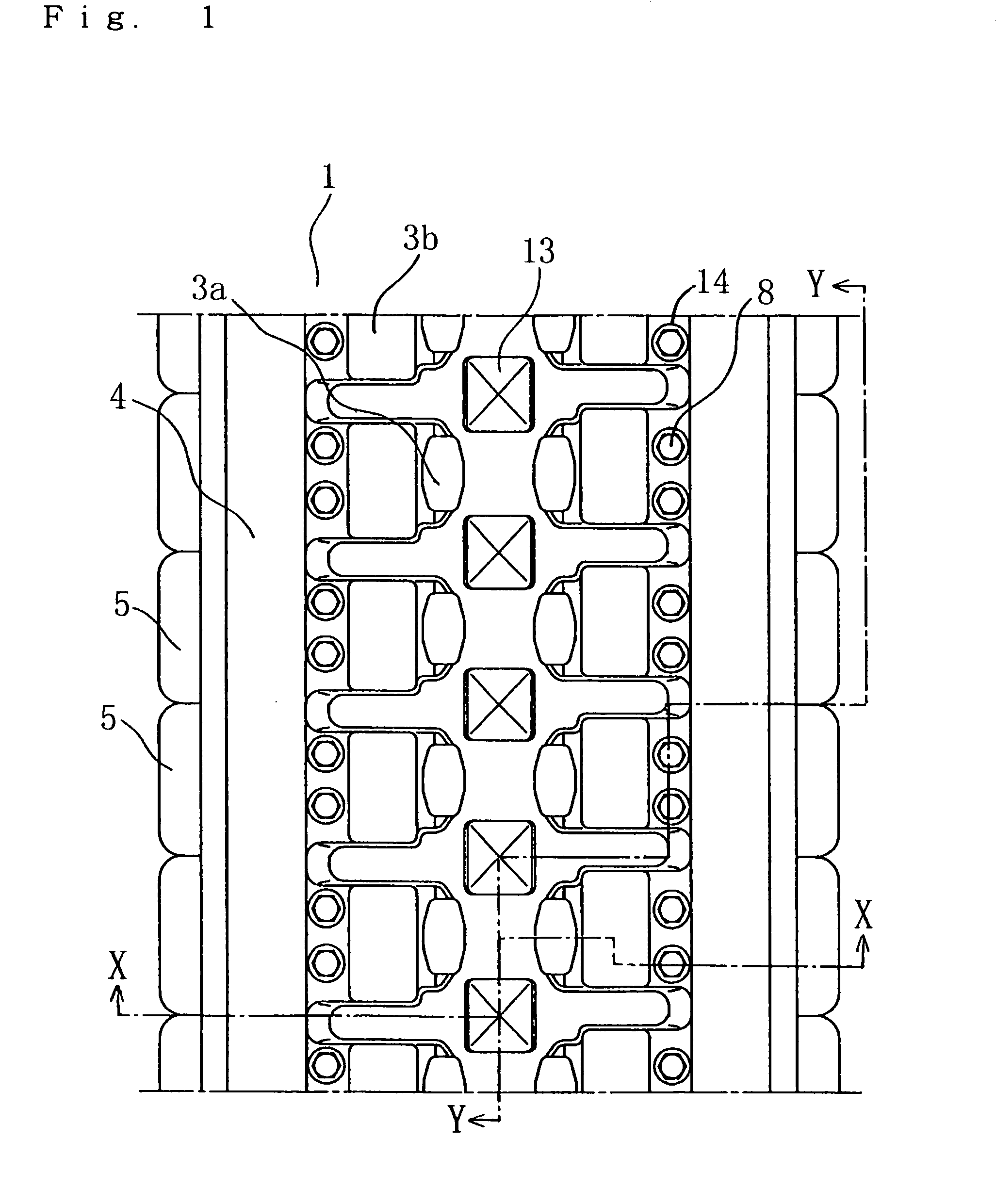
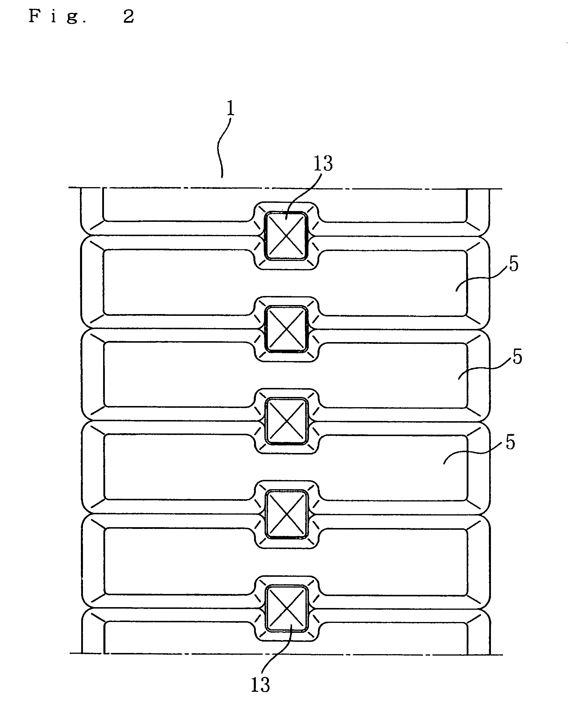
[0058]FIGS. 9 to 11 show a detachable rubber crawler 1 of the invention. FIG. 9 is a plan view showing the tread side (outer peripheral side) of the detachable rubber crawler 1, FIG. 10 is a section view taken on line X-X, and FIG. 11 is a section view taken on line Y-Y.
[0059]As for the detachable rubber crawler 1 of the second embodiment, a rubber pad 5 is the same size as a lug rubber part crossing two adjacent core bars 3 in the rubber belt 4. According to this, the lug rubber part of the rubber pad 5 can be enlarged, thereby improving durability.
[0060]Besides, the rubber pad 5 has a hole 13 for discharging mud at the center of the crawler width direction, and the portion sandwiched between the engaging holes serves as an inside lug 15 with low one step height.
third embodiment
[0061]Next, a detachable rubber crawler 1 of the third embodiment in the invention will be explained in reference with FIGS. 12 to 14.
[0062]As for the detachable rubber crawler 1 of the third embodiment, the rubber pad 5 in the second embodiment is divided into right and left portions from the center of the crawler width direction, and the divided right and left rubber pads 5 are shifted with respect to one another forward and rearward in the circumferential direction of the crawler in a staggered arrangement.
[0063]According to this, the rubber lug parts are arranged entirely in front and in rear in the crawler circumference direction. That is, the lug rubber part of the rubber pad 5 is at either the right or left side in the crawler width direction at the portion with low rigidity between the adjacent core bars 3 embedded in the rubber belt part 4. According to this, the rigidity of the crawler is uniform, thereby preventing the crawler from coming off of the travel device, and the...
PUM
 Abstract
Description
Claims
Application Information
 - R&D
- Intellectual Property
- Life Sciences
- Materials
- Tech Scout
- Unparalleled Data Quality
- Higher Quality Content
- 60% Fewer Hallucinations
Browse by: Latest US Patents, China's latest patents, Technical Efficacy Thesaurus, Application Domain, Technology Topic, Popular Technical Reports.
© 2025 PatSnap. All rights reserved.Legal|Privacy policy|Modern Slavery Act Transparency Statement|Sitemap|About US| Contact US: help@patsnap.com


