Radio frequency identification tags for digital storage discs

a technology of radio frequency identification and digital storage disc, which is applied in the field of identification tags, can solve the problems that many of the known rfid tag designs tend to be higher in cost, and achieve the effect of reducing the length of the linear dipole antenna

Inactive Publication Date: 2008-05-27
HITACHI AMERICA
View PDF10 Cites 20 Cited by
  • Summary
  • Abstract
  • Description
  • Claims
  • Application Information

AI Technical Summary

Benefits of technology

[0030]The present invention is directed to radio frequency identification (RFID) tags suitable for use on digital data storage discs, e.g., CDs and DVDs. Various RFID tags, in accordance with the present invention, include a RFID micro-chip coupled to a linear dipole antenna, with the linear dipole antenna being shorter in length than the optimal dipole antenna length associated with the RFID chip operating frequency, e.g., 2.45 GHz, in a free space environment. By using this shortened linear dipole antenna length, the shortened dipole antenna does not extend into the data region of the disc and does not interfere with normal disc data operations. In some embodiments, the ends of the linear dipole antenna are tapered to account for curvature of the edge of the hub area / data area interface. In addition by using a shortened linear dipole antenna, one can benefit from the advantages of scale, e.g., by adapting widely used mass produced currently available RFID tags using linear dipole antenna, such as the Hitachi mu-chip tag, e.g., by clipping the ends of the antenna and repackaging. Some RFID tags in accordance with the present invention utilize the metallization areas of the disc, e.g., a metallized hub area, to couple, e.g., through capacitance coupling, to the short length dipole antenna thus providing a complex antenna suitable for the operating frequency range of the RFID chip.
[0031]RFID disc tags, in accordance with the invention, are installed on a disc in the hub area, and are universally applicable to a wide range of disc applications including CDs, DVDs, HD DVD and Blu-Ray discs, with and without metallized hub areas. This universality of the RFID tag of the present invention, in addition to its low cost, makes the RFID tag of the present invention advantageous over other known custom RFID tag designs directed to a particular type of disc. For example, many of these known RFID tag designs tend to be higher in cost, e.g., due to a complex antenna design and / or due to low production, and work with one type of disc, e.g., a non-metallized hub disc, but do not typically work with metallized hub discs.
[0033]In various embodiments, an RFID tag in accordance with the present invention, includes adhesive material allowing the tag to be affixed to the disc. In some embodiments, the RFID tag includes a ring, e.g., a paper ring, for affixing the tag to the hub area of a disc. Some embodiments incorporate a peel off label into the RFID tag. In some embodiments, structural filler is included as part of the RFID tag so as to achieve substantially uniform thickness of the RFID tag and / or to prevent damage from crushing via clamping the RFID tag. In various embodiments, the RFID tag includes a circular overlay body which fits over the RFID chip. In some embodiments, the RFID chip / antenna in accordance with the invention, being very lightweight, adds insignificant weight to the disc from the perspective of disc imbalance at expected disc operating speeds, and additional counterbalance is not necessary. In various embodiments, one or more counterbalances is included in the tag to counterbalance the weight of the RFID microchip and linear dipole antenna. In some embodiments, one or more notches in the tag are provided to counterbalance the weight of the RFID microchip and linear dipole antenna.

Problems solved by technology

For example, many of these known RFID tag designs tend to be higher in cost, e.g., due to a complex antenna design and / or due to low production, and work with one type of disc, e.g., a non-metallized hub disc, but do not typically work with metallized hub discs.

Method used


Image

  • Radio frequency identification tags for digital storage discs
  • Radio frequency identification tags for digital storage discs
  • Radio frequency identification tags for digital storage discs

Examples


Embodiment Construction

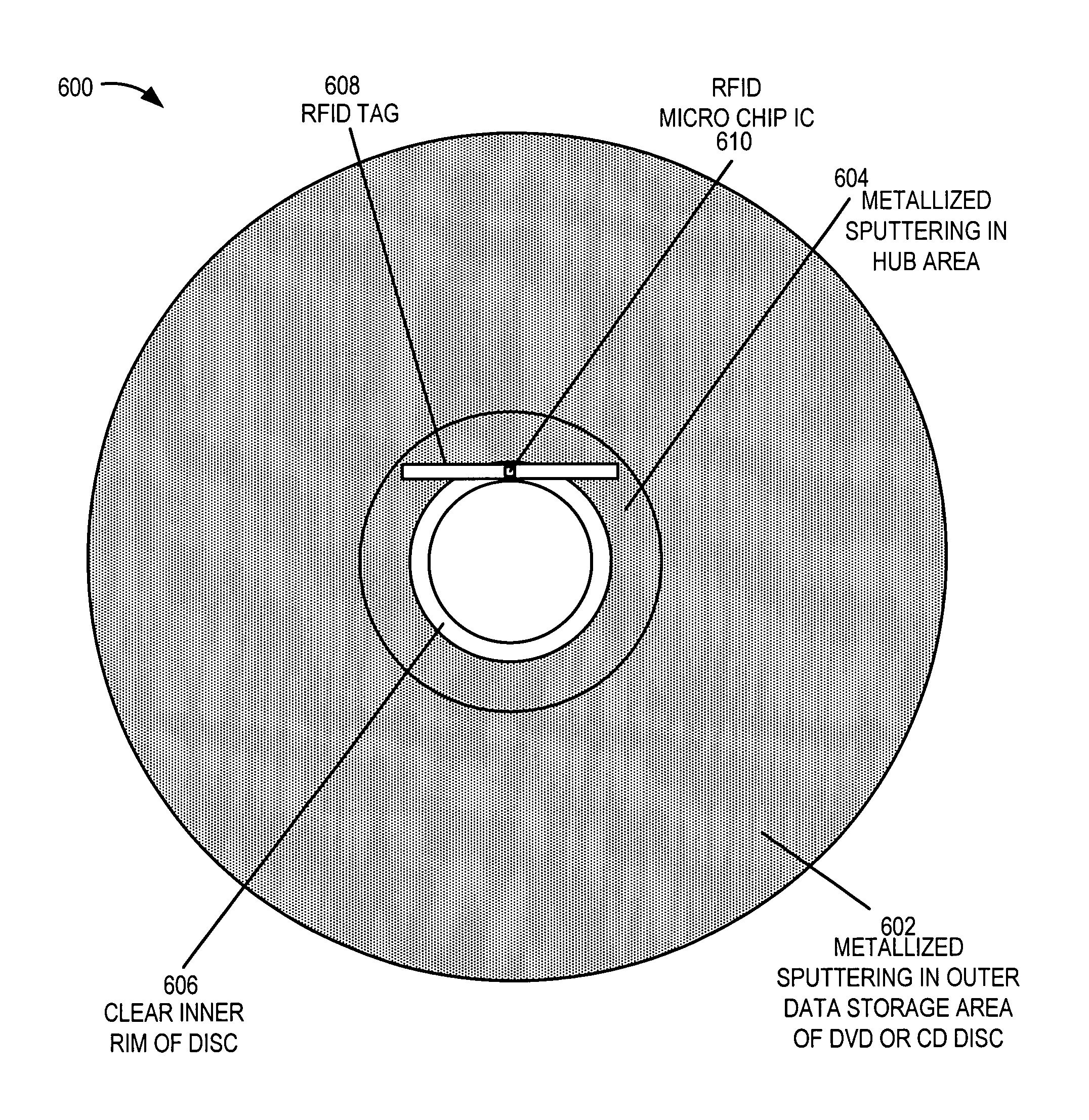
[0059]In order to overcome one or more of the obstacles of prior RFID systems, in some embodiments of the present invention, an existing RFID tag including a linear dipole antenna tuned to the RF carrier frequency is modified prior to use by preferably trimming equal lengths of the antenna at both ends so that the tag fits within the hub area of both a CD or a DVD without extending into the data area. In some embodiments of the present invention, an RFID in accordance with the present invention is manufactured such that the linear dipole antenna has a detuned antenna, with the manufactured antenna length being shorter than the length that would be selected to achieve optimal tuning for the operational frequency when operating in a free space environment, the tag length being such that the tag fits within the hub area of both a CD or a DVD without extending into the data area. In some such configurations, the RFID tag is positioned tangential to the central hole with the chip centere...


PUM

PropertyMeasurementUnit
lengthaaaaaaaaaa
frequencyaaaaaaaaaa
frequencyaaaaaaaaaa

Abstract

A universal low cost radio frequency identification (RFID) tag for use with data storage discs includes an RFID chip, e.g., 2.45 GHz mu-RFID chip, coupled to a linear dipole antenna. The antenna length is reduced in length from the expected length for an optimally tuned antenna corresponding to the operating radio frequency of the RFID chip in a free space environment. The antenna is placed in the tag such as to substantially overlap disc hub area and not extend into data area. The combination of the shortened linear dipole antenna and metallization on the disc to which the tag is applied effectively form a complex antenna operational in the RFID chip's frequency range. The RFID tag works on CDs and DVDs with and without substantially metallized hub areas. The RFID tag is less 0.3 mm thick and may include: ring shape, adhesive material, spacing material achieving uniform thickness, a counterbalance provision.

Description

RELATED APPLICATIONS[0001]The present application claims the benefit of U.S. Provisional Patent Application 60 / 615,491 filed Oct. 1, 2004 which is hereby expressly incorporated by reference.FIELD OF THE INVENTION[0002]The present invention relates generally to the field of identification tags and, more particularly, to the field of radio frequency identification tags for data digital storage discs such as, e.g., digital video discs.BACKGROUND OF THE INVENTION[0003]Radio Frequency identification (RFID) tags are increasingly being used to track multiple objects throughout a specified system. For example, RFID tags are being used on warehouse pallets to track the location of goods in a warehouse or verify the authenticity of tickets at a venue.[0004]An RFID tag is often implemented as a tiny integrated chip (IC) (hereinafter “mu-chip”) attached to an antenna. The IC stores a small amount of data, such as an. ID number, and the antenna is used to communicate with a reader. For example, ...

Claims


Application Information

Patent Timeline
Patent Type & Authority Patents(United States)
IPC IPC(8): G08B13/14G11B3/70G11B5/84
CPCG06K19/04G06K19/045G08B13/2445G11B23/0042H01Q9/20
Inventor ANDRECHAK, GARYWEILMEIER, MARTIN
Owner HITACHI AMERICA
Why Eureka
Try Eureka