
Micro movement pulsed radar system and method of phase noise compensation

a pulsed radar and micro movement technology, applied in the field of pulsed radar systems, can solve the problems of not having a known technique for effectively compensating for phase noise, the frequency of pulsed radars is not accurate, and the noise floor is reduced, so as to reduce the noise floor, reduce the bandwidth, and reduce the noise

Active Publication Date: 2008-05-27
RAYTHEON CO
View PDF10 Cites 12 Cited by
  • Summary
  • Abstract
  • Description
  • Claims
  • Application Information

AI Technical Summary

Benefits of technology

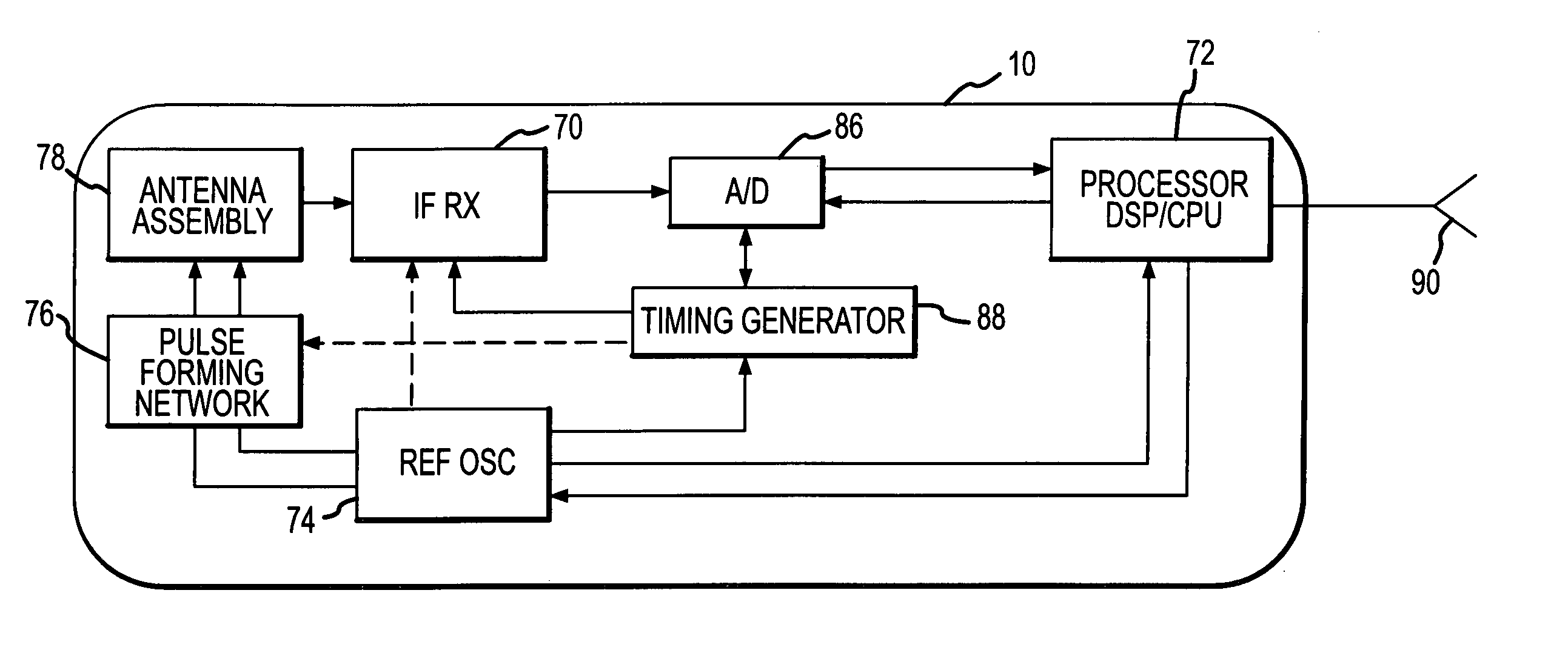
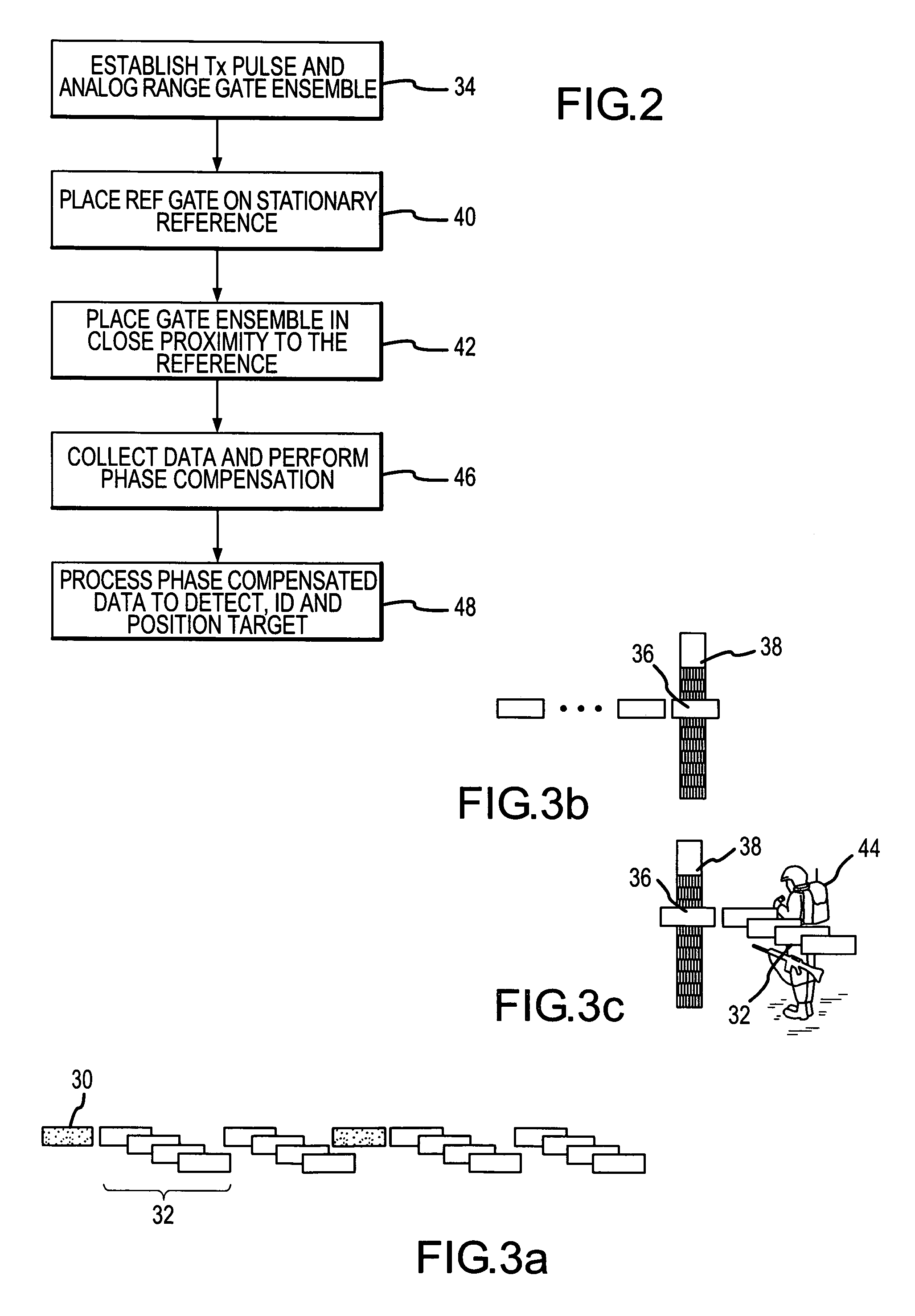
The present invention provides a pulsed radar system and method for detecting micro movements, particularly human motion, by using phase noise compensation to reduce noise. The system emits pulses and collects the return signals to position a reference range bin on a stationary reference. The system collects additional data to compute the phase shift of the return signal in the reference range bin with respect to its initial phase. The phase compensation reduces the noise floor significantly, allowing the system to detect micro-movements that would otherwise be buried in the noise. The system can detect movements at increased stand-off ranges. The noise level of the receiver must be low for effective phase compensation. The radar system can use an ensemble of analog range gates and narrow bandwidth A / D converters with low noise levels for the range gating function. The combination of narrowband A / D sampling and phase compensation reduces the noise floor so that micro-movements are detectable. The radar system can also use a high bandwidth and select a reference time sample with a large amplitude indicative of the stationary reference to compute the phase variation of the reference time sample with respect to its initial phase. The application of phase compensation to these existing designs will lower the noise floor so that micro-movements are detectable.

Problems solved by technology

Pulsed radar systems do not compensate for phase noise other than to stabilize the oscillator to the degree possible.
First, the phase noise is typically overshadowed by the system noise associated with the A / D converter and receiver.
Second, until recently most radar applications were directed to targets at long stand-off ranges having a large radar cross-section and large Doppler frequency.
Finally, there is no known technique for effectively compensating for phase noise.
Such attempts have been unsuccessful because the target signatures associated with “micro movement” are buried in the overall system noise and even the phase noise.
This may be adequate in non-hostile environments but is not acceptable under battlefield conditions.

Method used


Image

  • Micro movement pulsed radar system and method of phase noise compensation
  • Micro movement pulsed radar system and method of phase noise compensation
  • Micro movement pulsed radar system and method of phase noise compensation

Examples


Embodiment Construction

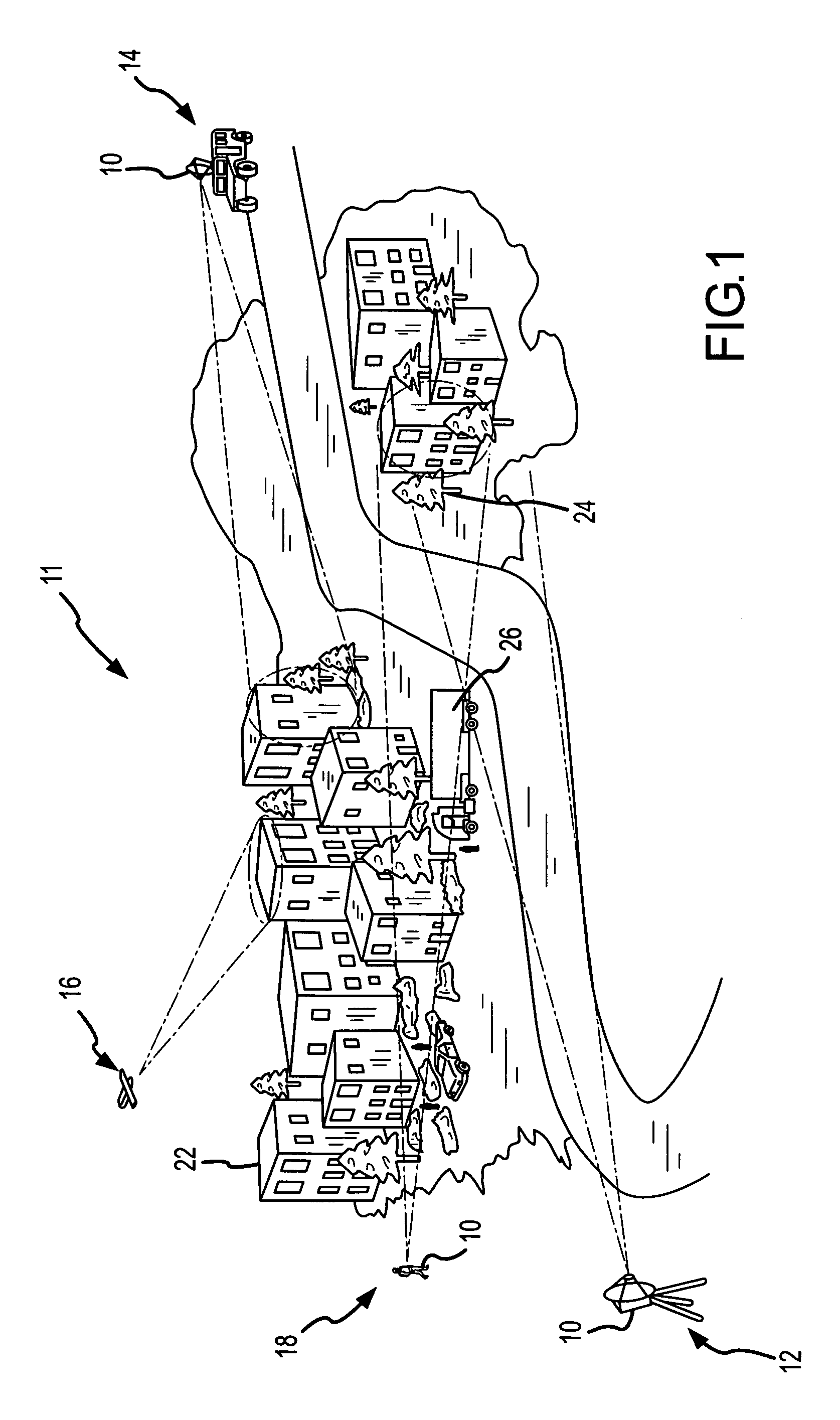
[0026]The present invention describes a pulsed radar system and method of detecting micro movements and particularly human motion such as walking, breathing or heartbeat. This is accomplished by using phase noise compensation to reduce noise due to drift of the reference oscillator. The noise level due to A / D sampling must be sufficiently low for the phase noise compensation to be effective. As this is currently beyond state-of-the-art for high bandwidth A / D converters used in traditional receiver design, the receiver is suitably reconfigured to use analog range gates and narrowband A / D sampling having sufficiently low noise level as described in FIGS. 2-9. As technology continues to improve A / D and receiver components, the phase compensation techniques may be directly applicable to the high bandwidth A / D samples in traditional receiver designs as described in FIGS. 10-11. Whether phase compensation is applied to traditional receiver designs or a receiver configured with analog rang...


PUM


Abstract

A pulsed radar system uses phase noise compensation to reduce phase noise due to drift of the reference oscillator to enable detection of micro movements and particularly human motion such as walking, breathing or heartbeat. The noise level due to A / D sampling must be sufficiently low for the phase noise compensation to be effective. As this is currently beyond state-of-the-art for high bandwidth A / D converters used in traditional receiver design, the receiver is suitably reconfigured to use analog range gates and narrowband A / D sampling having sufficiently low noise level. As technology continues to improve, the phase compensation techniques may be directly applicable to the high bandwidth A / D samples in traditional receiver designs. Whether phase compensation is applied to traditional receiver designs or a receiver configured with analog range gates, the steps are essentially the same: data is processed to position a reference range bin (either an analog range gate or a particular time sample) on a stationary reference and the phase variation of that reference range bin is used to compensate the phase of target data in range bins (either an ensemble of range gates or other time samples) near the stationary reference. This effectively moves the radar system and particularly the reference oscillator to the stationary reference thereby greatly reducing oscillator drift and phase noise and decoupling the stand-off range from the level of phase noise.

Description

BACKGROUND OF THE INVENTION[0001]1. Field of the Invention[0002]This invention relates to pulsed radar systems, and more specifically to a radar system and method of phase noise compensation capable of detecting micro movement.[0003]2. Description of the Related Art[0004]Doppler radar is used to measure both the range to target and the “doppler” movement of the target. Pulsed radar system emit pulses and A / D sample the return pulses to extract range and movement of the target. The pulses may be single-frequency pulses or more recently stepped frequency pulses. Typically, the pulses are in the RF band, approximately 4-100 nsec. Experimental “impulse” systems transmit very short pulses, less than 1 nsec to achieve instantaneous high range resolution. In each of these cases, the bandwidth of the A / D converter is quite high, 100 Mhz range for pulsed RF and 1 Ghz for impulse systems. Such high bandwidth A / D converters typically have a spur free dynamic range of no better than 60 dB and 3...

Claims


Application Information

Patent Timeline
Patent Type & Authority Patents(United States)
IPC IPC(8): G01S7/292G01S13/50G01S13/00
CPCG01S13/18G01S13/522G01S13/56
Inventor DWELLY, WESLEY H.ADAMS, VINH N.
Owner RAYTHEON CO
Learn More