Correction apparatus

a technology of correction apparatus and level difference, which is applied in the field of correction apparatus, can solve the problems of power consumption increase, s/n ratio decrease, image quality degradation, etc., and achieve the effect of reducing a level difference and reducing the level differen

Inactive Publication Date: 2008-05-27
CANON KK
View PDF16 Cites 53 Cited by
  • Summary
  • Abstract
  • Description
  • Claims
  • Application Information

AI Technical Summary

Benefits of technology

[0021]It is still another object of the present invention to quickly cope with dynamic variations such as the shake of an image sensing apparatus and correct the non uniformity between a plurality of image sensing regions in real time.
[0053]wherein in the level adjustment process, the correction coefficient determined in the correction coefficient determination process is used to perform adjustment so as to reduce the level difference between the plurality of image sensing signals.

Problems solved by technology

If pieces of information of all pixels are read out, the S / N ratio decreases and the power consumption increases.
The drawback of this method is degradation in image quality such that, when two regions are synthesized to generate an image, a boundary line is generated by the level difference between the regions owing to the non uniformity between the characteristics of the amplifiers and external peripheral circuits in these regions.
However, in the prior art, correction cannot be performed in real time because the correction coefficient is calculated only under predetermined conditions such that a standard white image is sensed.
The prior art cannot cope with dynamic variations such as temperature variations or variations over time, or variations in the focusing degree of the image sensing optical system, failing to sufficiently correct the non uniformity between regions.
Also, the prior art cannot quickly cope with dynamic variations such as the shake of an image sensing apparatus, and cannot satisfactorily correct the non uniformity between regions.

Method used


Image

  • Correction apparatus
  • Correction apparatus
  • Correction apparatus

Examples


first embodiment

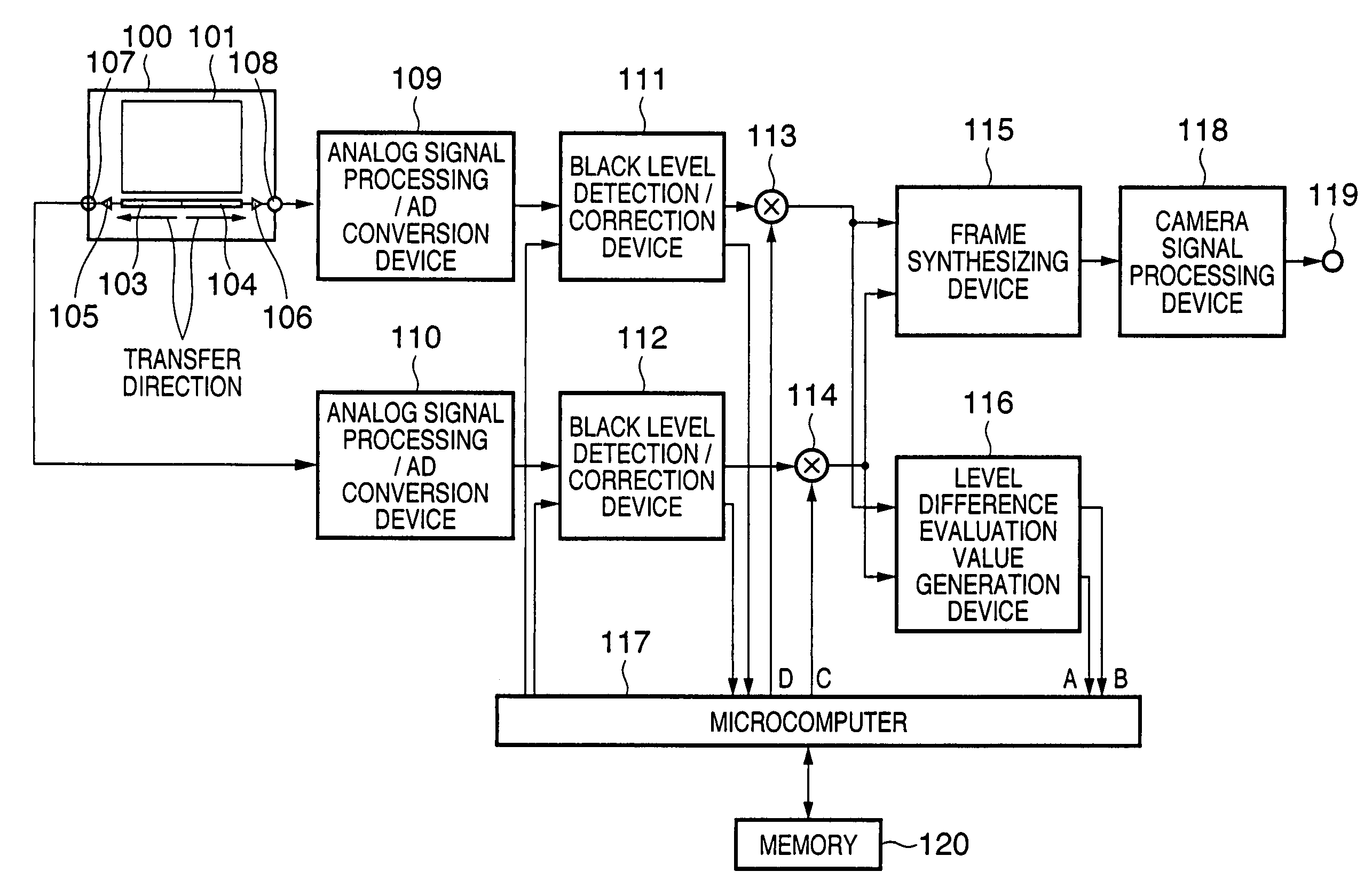
[0088]FIG. 1 is a block diagram schematically showing an embodiment in which a correction apparatus according to the present invention is applied to a single-CCD video camera.

[0089]In FIG. 1, reference numeral 100 denotes a CCD area sensor in which the image sensing region is divided into two and each region has an output terminal; 101, a photoelectric conversion / vertical transfer unit; and 103 and 104, horizontal transfer units which are arranged in left and right directions using the center of the screen as a boundary.

[0090]Reference numerals 105 and 106 denote output amplifiers which amplify signal charges; and 107 and 108, image sensing signal output terminals. Reference numerals 109 and 110 denote analog front ends which perform correlated double sampling and A / D conversion. Reference numerals 111 and 112 denote black level detection / correction devices; 113 and 114, gain adjustment devices which adjust the gain; and 115, a frame synthesizing device which synthesizes two image s...

second embodiment

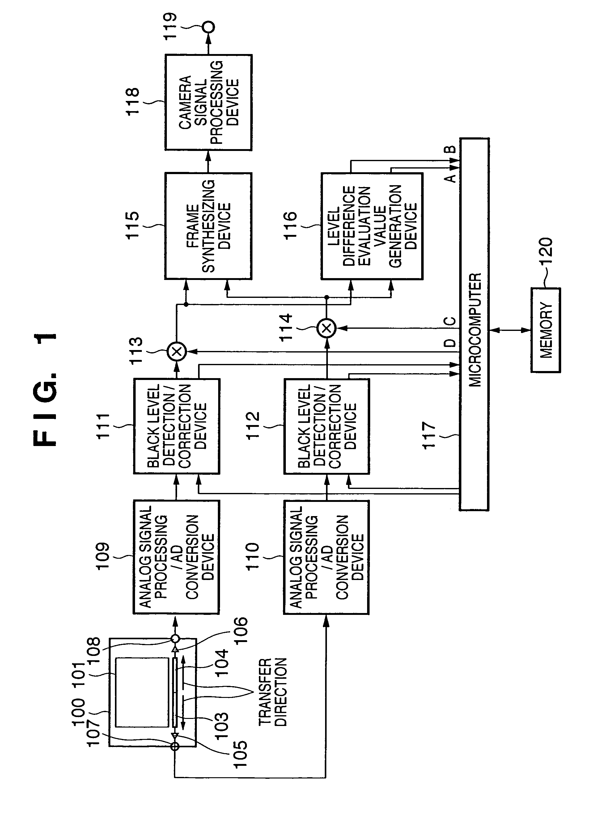
[0127]FIG. 8 is a signal processing block diagram for explaining a correction apparatus according to the second embodiment of the present invention. The detailed arrangement of an overall image sensing apparatus is the same as that in the first embodiment. Signal processes shown in FIG. 8 are executed within a microcomputer 117 in FIG. 1. Also, a rectangular region for evaluation value measurement is the same as that in the first embodiment.

[0128]The gain error between two systems is not constant for the output level of a CCD 100, as shown in FIG. 3. A natural image in general photographing contains objects with various brightnesses. If the gain error is measured from a general natural image, a value obtained by multiplying the gain error characteristic curve shown in FIG. 3 by a brightness distribution frequency within a rectangular region and integrating the product is obtained, failing to calculate an accurate gain error amount. To prevent this, the second embodiment considers th...

third embodiment

[0136]FIG. 11 is a block diagram showing the third embodiment of the present invention and showing an arrangement example of an apparatus which performs signal processes in an image sensing apparatus. The detailed arrangement of the whole image sensing apparatus is the same as that in the first embodiment. FIG. 11 shows an arrangement example of a level difference evaluation value generation device 116 in FIG. 1. A rectangular region for evaluation value measurement is the same as that in the first embodiment.

[0137]As described above, the gain error between two systems is not constant for the output level of a CCD 100. If the level difference is measured from a general natural image, no accurate gain error amount may be calculated. To prevent this, the third embodiment considers the image brightness.

[0138]Outputs from gain adjustment devices 113 and 114 correspond to a left channel input and right channel input in FIG. 11, respectively. Since the right and left channels have a commo...


PUM


Abstract

An object of this invention is to correct the non uniformity between a plurality of image sensing regions in real time and cope with even dynamic variations such as temperature variations or variations over time. To achieve this object, a correction apparatus includes a plurality of level adjustment devices which independently adjust the levels of a plurality of image sensing signals output from a plurality of output terminals, an output level detection device which detects the output levels of the plurality of level adjustment devices, and a correction coefficient determination device which determines a correction coefficient for reducing the level difference between the image sensing signals on the basis of the detection result of the output level detection device. The correction coefficient determination device determines the correction coefficient by excluding an object-dependent level difference component in which the level difference between the plurality of image sensing signals exceeds a predetermined level difference. The correction coefficient determination device supplies the determined correction coefficient to the level adjustment devices to perform adjustment so as to reduce the level difference between the image sensing signals.

Description

FIELD OF THE INVENTION[0001]The present invention relates to a correction apparatus and, more particularly, to a correction apparatus which corrects a signal from a solid-state image sensing element that has an image sensing plane divided into a plurality of regions and comprises an amplifier for amplifying image sensing signals from the respective regions and a plurality of image sensing signal output terminals connected to the output of the amplifier.BACKGROUND OF THE INVENTION[0002]With recent development of the digital signal processing technique and semiconductor technique, there is proposed a consumer digital video standard of recording a standard television signal such as an NTSC or PAL moving picture signal as a digital signal. As its application, digital video cameras formed by integrating a digital video recording / playback apparatus and image sensing apparatus are commercially available. Some digital video cameras have a still picture recording function by exploiting the f...

Claims


Application Information

Patent Timeline
Patent Type & Authority Patents(United States)
IPC IPC(8): H04N5/217H04N5/225H04N5/228
CPCH04N5/23248H04N5/3653H04N23/68H04N25/41H04N25/672
Inventor HATTORI, YUUICHIROUINOU, KAZUYA
Owner CANON KK
Why Eureka
Try Eureka