

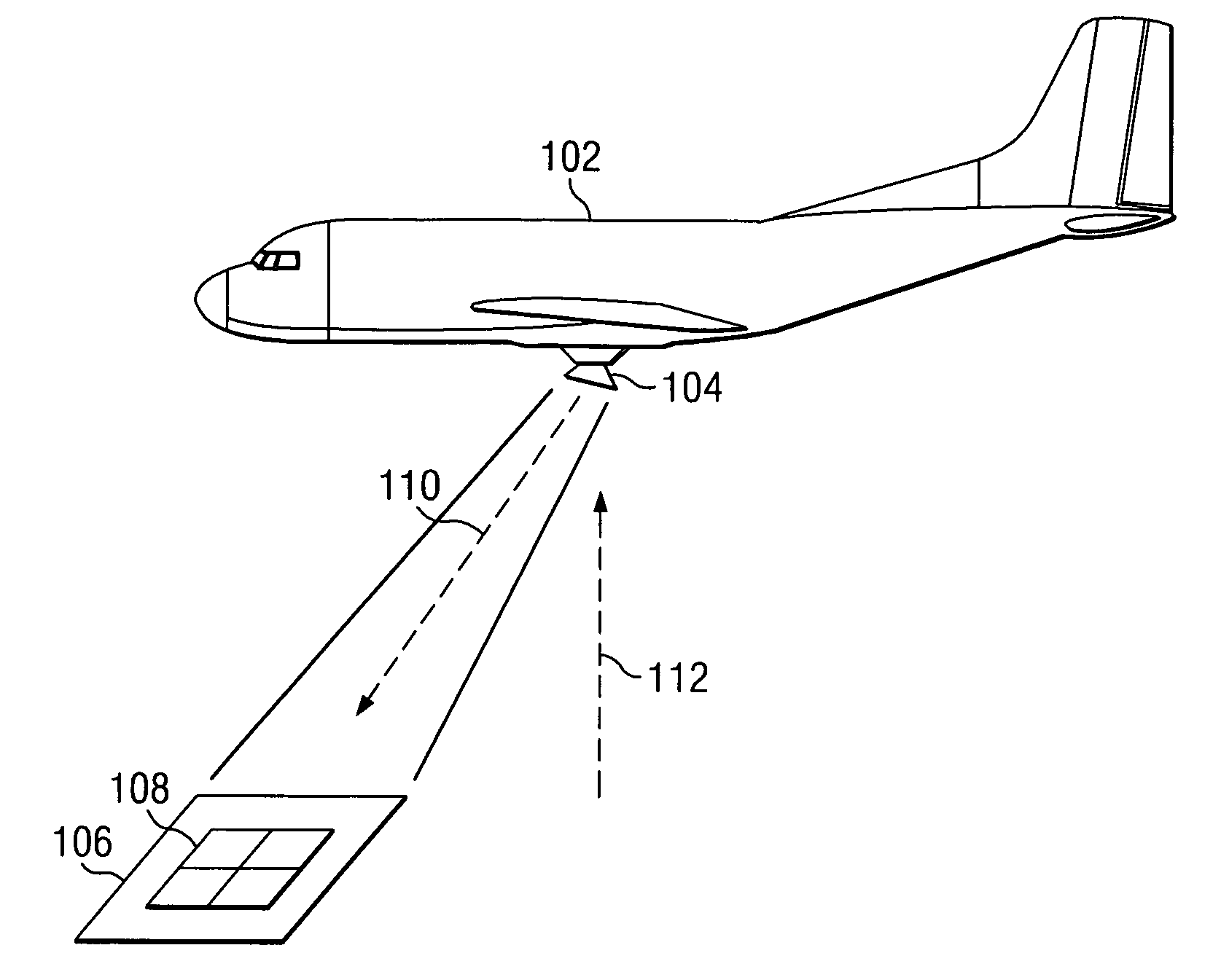
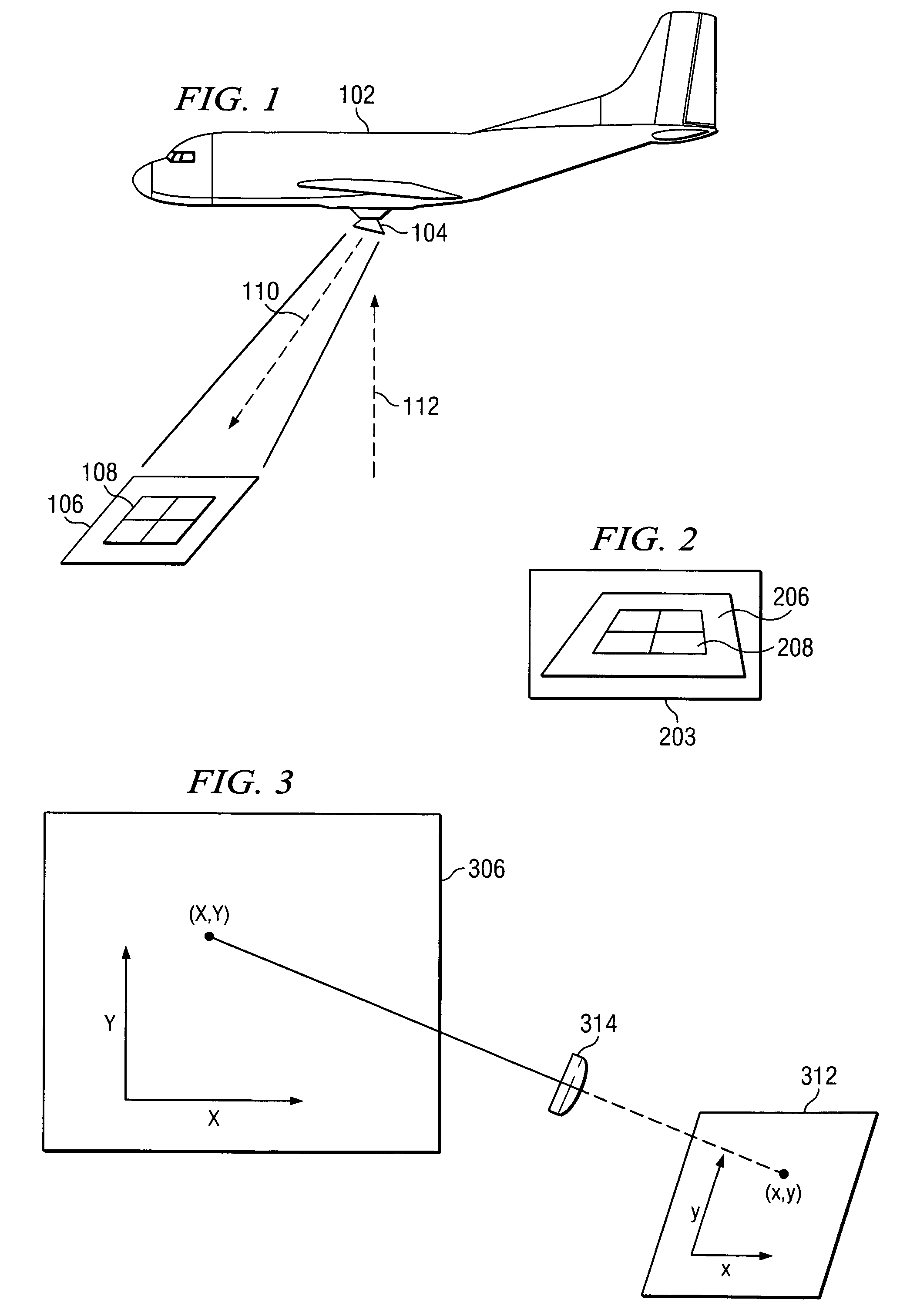
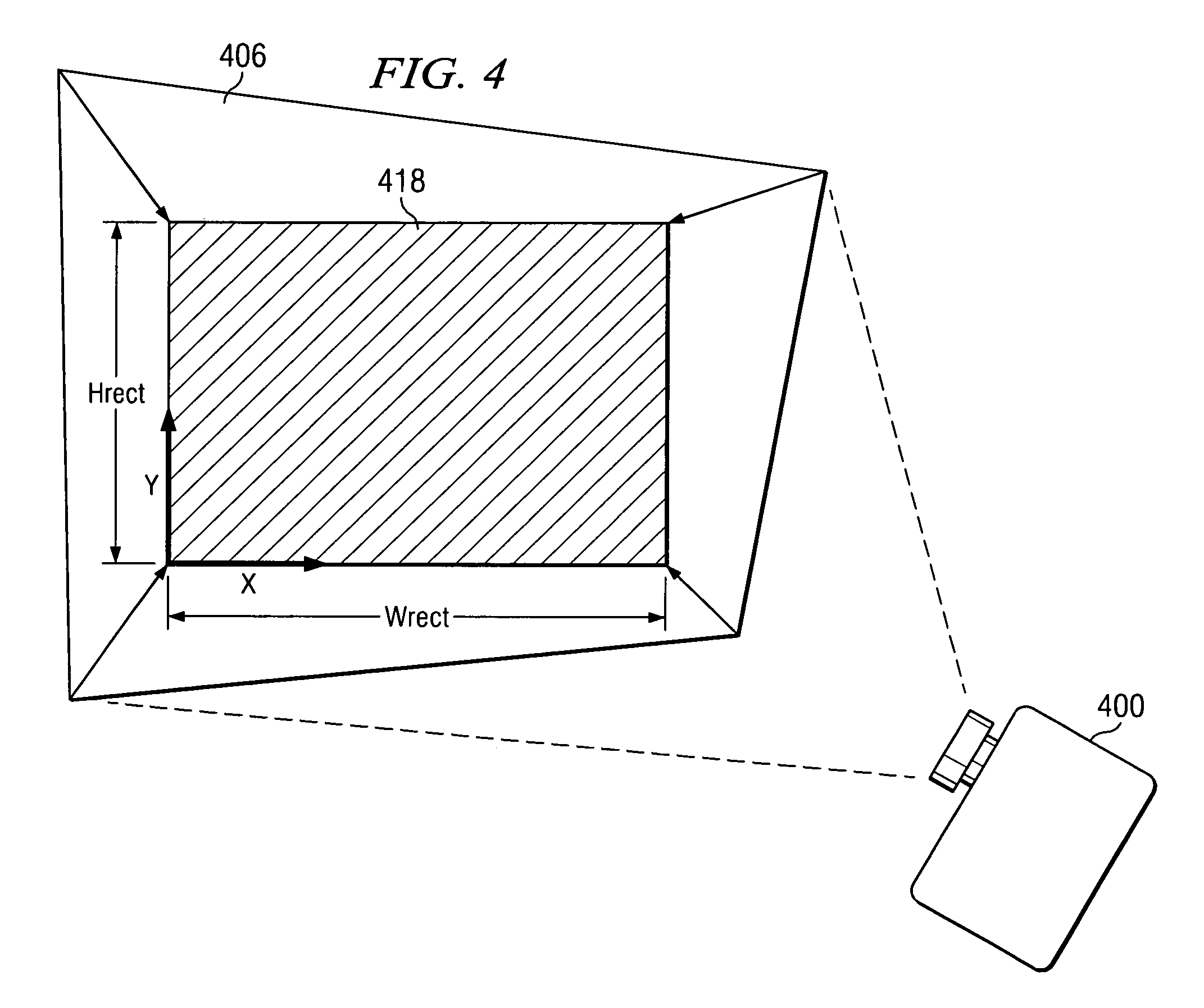
System and method for two-dimensional keystone correction for aerial imaging
a two-dimensional keystone correction and aerial imaging technology, applied in image enhancement, image analysis, visual presentation, etc., can solve the problems of keystone distortion or rotation of recorded images, geometric skewing of locations, distortion between adjacent images, etc., and achieve accurate location and not computationally intensive effects
- Summary
- Abstract
- Description
- Claims
- Application Information
AI Technical Summary
Benefits of technology
Problems solved by technology
Method used
Image

Examples
Embodiment Construction
[0021]The making and using of the presently preferred embodiments are discussed in detail below. It should be appreciated, however, that the present invention provides many applicable inventive concepts that can be embodied in a wide variety of specific contexts. The specific embodiments discussed are merely illustrative of specific ways to make and use the invention, and do not limit the scope of the invention.
[0022]The present invention will be described with respect to preferred embodiments in a specific context, namely an image keystone correction system such as one utilizing a camera or electronic image recording process that acquires images of an object with one or more axes of the subject plane misaligned to one or more axes of the camera or electronic image recording process. The image keystone correction process locates image points for the corrected image using a geometric transformation that computes the distances of two constructed intercept points in the distorted image...
PUM
 Abstract
Description
Claims
Application Information