Method for monitoring the speed of a bi-turbocharger

a technology of rotating speed and bi-turbocharger, which is applied in the direction of mechanical equipment, machines/engines, electric control, etc., can solve the problems of mechanical overload, reduce power, and monitor the rotational speed of a bi-turbocharger

Inactive Publication Date: 2008-06-03
CONTINENTAL AUTOMOTIVE GMBH
View PDF14 Cites 24 Cited by
  • Summary
  • Abstract
  • Description
  • Claims
  • Application Information

AI Technical Summary

Benefits of technology

[0017]Thus, in the case of a large difference in rotational speed between the two exhaust gas turbochargers, it is for example possible to open a bypass valve (waste gate) which bypasses the exhaust gas turbine of the exhaust gas turbocharger which is functioning correctly and thereby reduces its power in order to prevent an overload situation.
[0019]The further possible protective measure exists of limiting the maximum opening of the throttle valve in order to prevent any overloading of an exhaust gas turbocharger in the event of a fault.

Problems solved by technology

In the case of such a single-sided drop in power affecting the bi-turbocharger, the other exhaust gas turbocharger will deliver a correspondingly greater volume flow in this situation, which can lead to mechanical overloading as a result of the increased rotational speed of the exhaust gas turbocharger which is functioning correctly.
For example, in such an instance a bypass valve (waste gate) can be opened which bypasses the exhaust gas turbine of the exhaust gas turbocharger which is functioning correctly and thereby reduces its power.
The disadvantage of the known method described above for monitoring the rotational speed of a bi-turbocharger is the fact that a pressure sensor is required in the exhaust section of each of the two cylinder banks.

Method used


Image

  • Method for monitoring the speed of a bi-turbocharger
  • Method for monitoring the speed of a bi-turbocharger
  • Method for monitoring the speed of a bi-turbocharger

Examples


Embodiment Construction

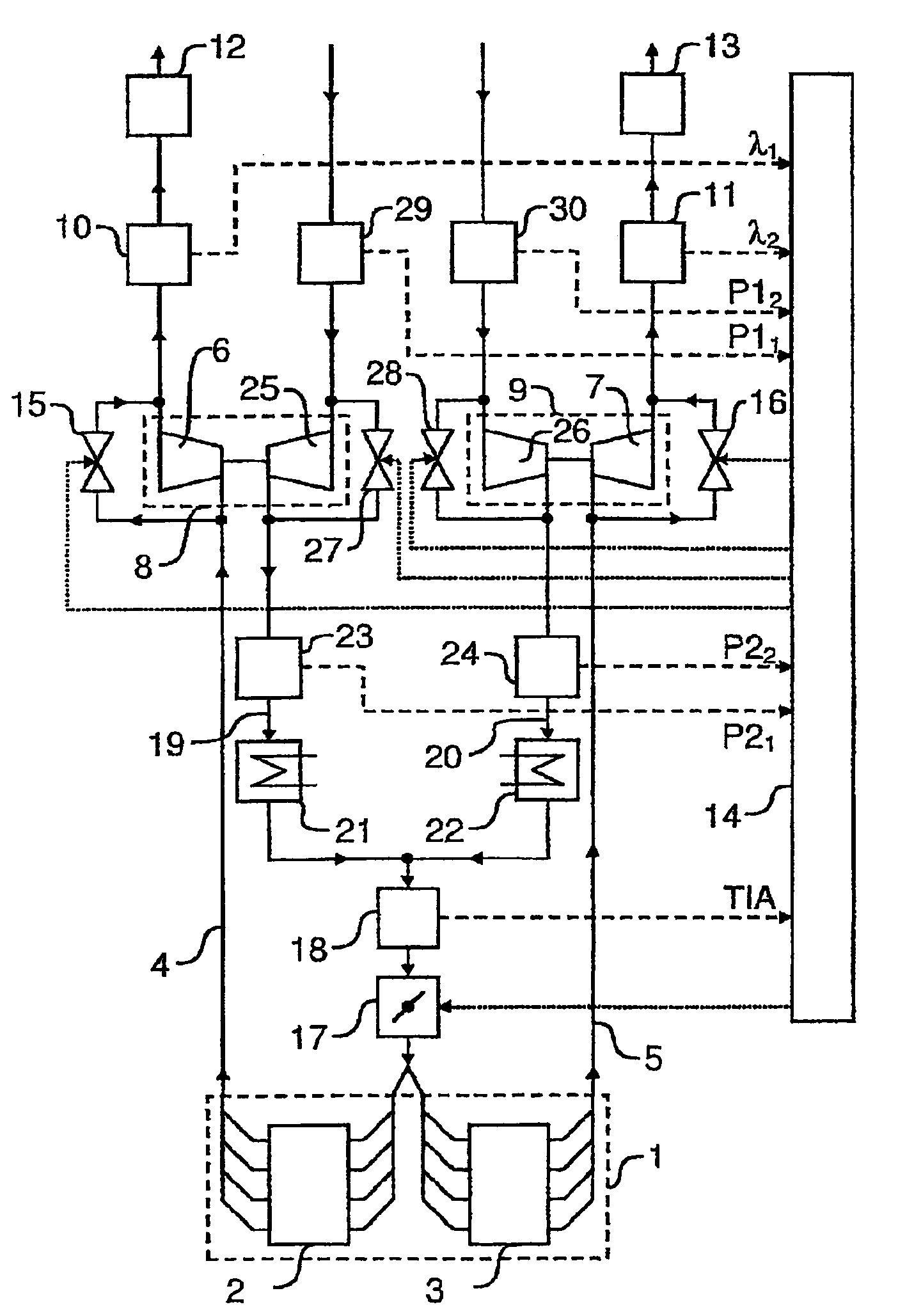
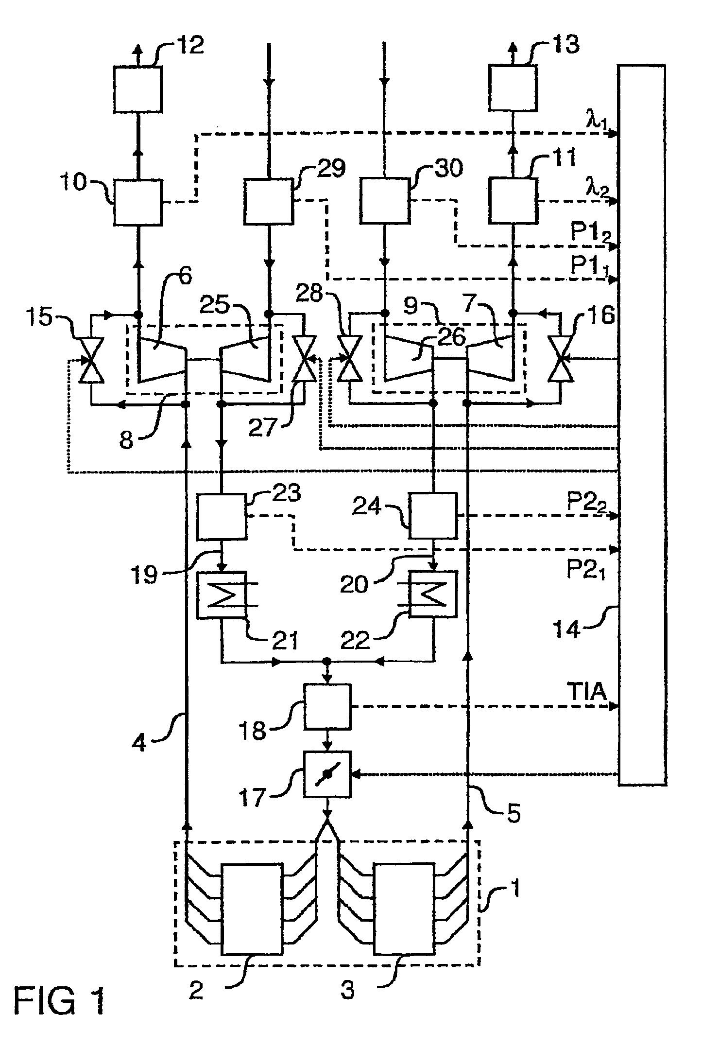
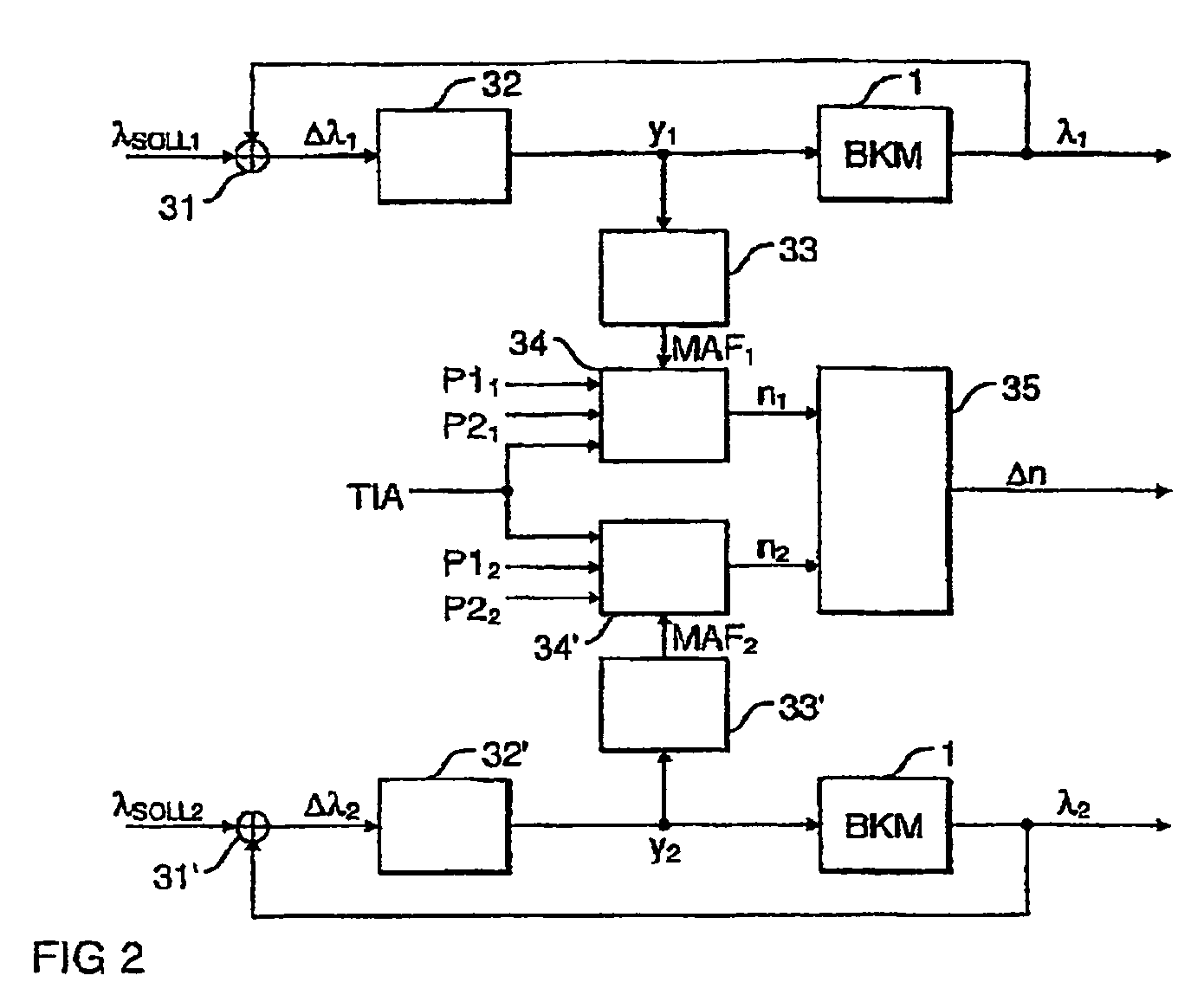
[0039]In the following, the structure of the bi-turbocharger arrangement shown in FIG. 1 is described initially in order to subsequently describe the method according to the invention with reference to the control engineering equivalent circuit diagram shown in FIG. 2 and the flowchart shown in FIGS. 3a to 3c.

[0040]FIG. 1 shows an internal combustion engine 1 with two cylinder banks 2, 3 each having four cylinders. Within the framework of the invention it is however also possible for each of the two cylinder banks 2, 3 to have a different number of cylinders. Each of the two cylinder banks 2, 3 can thus, for example in the case of a 6-cylinder engine, have three cylinders.

[0041]For each of the two cylinder banks 2, 3 the internal combustion engine 1 has a separate exhaust section 4, 5, whereby the exhaust section 4 is connected to an exhaust turbine 6 of an exhaust gas turbocharger 8, while the exhaust section 5 is connected to an exhaust turbine 7 of an exhaust gas turbocharger 9....


PUM


Abstract

A method and a device for monitoring a rotational speed of a first charger for an internal combustion engine, especially an exhaust gas turbocharger, are provided. A first exhaust value representing an exhaust gas composition of the internal combustion engine in a first exhaust section is defined, and a first speed value representing the rotational speed of the first charger is determined according to the defined first exhaust value. The first exhaust value is regulated to a predefined first reference value using a first correcting variable which is ascertained as required for regulation. The first rotational speed value is determined depending on the first correcting variable.

Description

CROSS REFERENCE TO RELATED APPLICATION[0001]This application is the U.S. National Stage of International Application No. PCT / EP2004 / 050630, filed Apr. 28, 2004 and claims the benefit thereof. The International Application claims the benefits of German Patent application No. 103 20 977.8 DE filed May 9, 2003, both of the applications are incorporated by reference herein in their entirety.FIELD OF THE INVENTION[0002]The invention relates to a method and a device for monitoring the rotational speed of a bi-turbocharger for an internal combustion engine.BACKGROUND OF THE INVENTION[0003]Internal combustion engines having two separate banks of cylinders are known, where in each case an exhaust gas turbocharger is assigned to each cylinder bank. The two exhaust gas turbochargers consist in each case of an exhaust turbine located in the exhaust section of the two cylinder banks and a compressor which is located in the intake section of the two cylinder banks and increases the charging press...

Claims


Application Information

Patent Timeline
Patent Type & Authority Patents(United States)
IPC IPC(8): F02B33/44F02B29/04F02B37/007F02B37/16F02B37/18F02D23/00F02D41/00F02D41/14F02D41/22
CPCF02B37/007F02B37/16F02B37/18F02D23/00F02D41/0007F02D41/1443F02D41/22F02D41/221F01N13/107F02B29/0412Y02T10/40Y02T10/144Y02T10/12
Inventor HENN, MICHAELKUNZ, FRANZZHANG, HONG
Owner CONTINENTAL AUTOMOTIVE GMBH
Why Eureka
Try Eureka