Compressor

Active Publication Date: 2008-06-03
LG ELECTRONICS INC
View PDF9 Cites 9 Cited by
  • Summary
  • Abstract
  • Description
  • Claims
  • Application Information

AI Technical Summary

Benefits of technology

[0028]An object of the present invention lies on reducing a friction loss occurred when a piston and a cylinder make relative movement, to enhance an efficiency of a compressor.
[0029]Another object of the present invention lies on minimizing a dead volume occurred when the piston is at a top dead center, to enhance a compression efficiency.

Problems solved by technology

In this instance, an inside wall of the cylinder 10, and an outside surface of the piston cause friction on each other, which drops an efficiency of the compressor due to a friction loss taken place in this time.
The dead volume formed thus drops the efficiency of the compressor.

Method used


Image

  • Compressor
  • Compressor
  • Compressor

Examples


Embodiment Construction

[0055]Reference will now be made in detail to the preferred embodiments of the present invention, examples of which are illustrated in the accompanying drawings. In describing the embodiments, same parts will be given the same names and reference symbols, and repetitive description of which will be omitted.

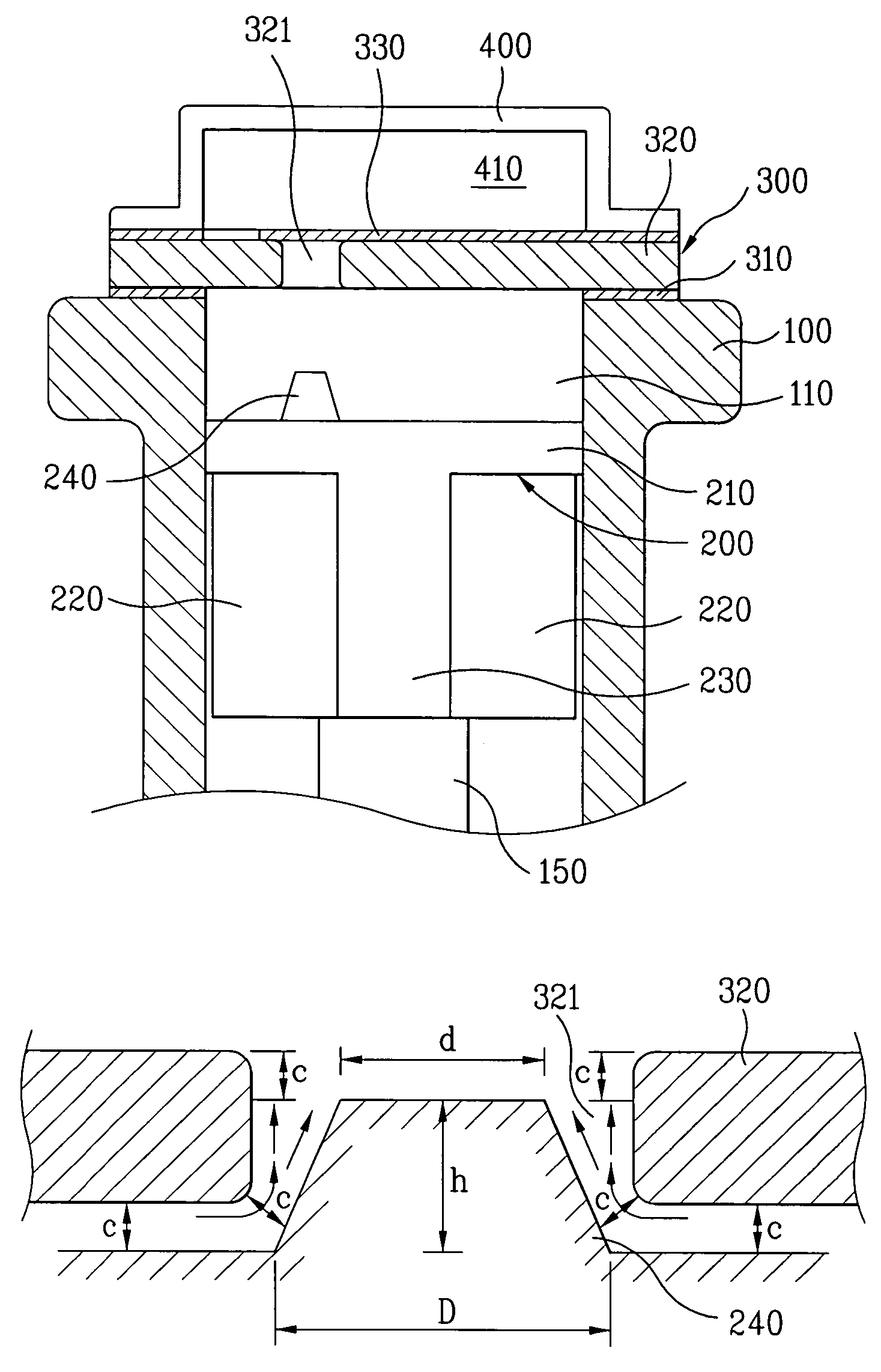
[0056]Referring to FIG. 3, there is a cylinder having opened opposite ends, with a piston 200 of the present invention inserted therein. The piston 200 is coupled to one end of a connecting rod 150 inserted in the cylinder 100 through one of the opened ends of the cylinder 100, for an example, a lower end. For this, as shown in FIG. 4, the cylinder 100 has a pin hole 225, so that the piston (not shown) is passed through the pin hole 225 and the one end of the connecting rod 150 at the same time. Meanwhile, the other end of the connecting rod 150 is connected to the crankshaft (not shown) rotated by the motor (not shown).

[0057]The connecting rod 150, connecting the crankshaft and t...


PUM


Abstract

A reciprocating compressor is provided that includes a compression chamber inside of a cylinder and a piston inserted therein. The piston includes a head, a skirt extended from a lower end of the head so as to be spaced away from an inside wall of the cylinder, and guide surfaces extended from an outside surface of the skirt. Since the skirt is not in contact with the cylinder, a friction loss between the piston and the cylinder is reduced, and the guide surfaces assist the piston to make stable reciprocation. The head has a projection so as to be inserted into a discharge hole when the piston is at a top dead center. According to this, a dead volume formed when the piston is at the top dead center is reduced, thereby improving an efficiency of the compressor.

Description

[0001]This application claims the benefit of the Korean Application No. P2003-38430 filed on Jun. 13, 2003, which is hereby incorporated by reference.BACKGROUND OF THE INVENTION[0002]1. Field of the Invention[0003]The present invention relates to compressors, and more particularly, to a reciprocating compressor having a piston for reciprocating in a cylinder to compress a working fluid.[0004]2. Background of the Related Art[0005]The compressor boosts a pressure of the working fluid by receiving a power from an electric motor or a turbine, and applying a compressive work to air, refrigerant, or other special gas. The compressor is widely used starting from home appliances, to plant industries in the fields of air conditioners, or refrigerators.[0006]Depending on methods of compression, there are positive displacement compressors, and dynamic compressors, or turbo compressors. In the positive displacement compressors for boosting a pressure by reduction of a volume, there are reciproc...

Claims


Application Information

Patent Timeline
IPC IPC(8): F16J1/04F04B39/00F04B39/10
CPCF04B39/0005F04B39/1073F04B39/00F04B39/02
Inventor PARK, DONG WOOJUNG, MIN KYU
Owner LG ELECTRONICS INC
Why Eureka
Try Eureka