Mega flow system

a flow system and micro-flow technology, applied in the field of aquaculture systems, can solve the problems of limited bio-density, limited bio-density, and limited maximum bio-density

Inactive Publication Date: 2008-06-03
HADDAS ISRAEL
View PDF23 Cites 52 Cited by
  • Summary
  • Abstract
  • Description
  • Claims
  • Application Information

AI Technical Summary

Benefits of technology

[0018]According to a further feature of the present invention, the airlift pump includes a second air dispensing arrangement disposed externally to the conduit, the second dispensing arrangement being configured to regulate the rate of water flow in the conduit, thereby regulating the amount of aeration of the water.
[0025]According to a further feature of the present invention, there is also provided a separation arrangement disposed between the culture tank and the aeration device substantially at the end of the first flow path, the separation arrangement being configured to filter water leaving the culture tank to prevent clogging of the aeration device.
[0035]According to a further feature of the present invention, there is also provided an adjustable choke configured to regulate the rate of water flow in the conduit, thereby regulating the amount of aeration of the water.
[0036]According to a further feature of the present invention, there is also provided a second air dispensing arrangement disposed externally to the conduit, the second dispensing arrangement being configured to regulate the rate of water flow in the conduit, thereby regulating the amount of aeration of the water.

Problems solved by technology

Other methods relying on aeration apparatus such as paddle wheels, surface agitators, and air diffusers, limit maximum bio-density.
Bio-density is limited due to the narrow band available for oxygen introduction between saturation and the minimal concentration required for the well being of the reared species.
Bio-density is also limited due to the maximum velocity and turbulence created by such apparatus, limiting its use and creating a maximum density barrier derived from the rate of oxygen consumption and the maximum allowable speed and turbulence.

Method used


Image

  • Mega flow system
  • Mega flow system
  • Mega flow system

Examples


Embodiment Construction

[0054]The present invention is an aerated recirculated aquaculture system construction and method of operation thereof.

[0055]The principles and operation of an aerated recirculated aquaculture system according to the present invention may be better understood with reference to the drawings and the accompanying description.

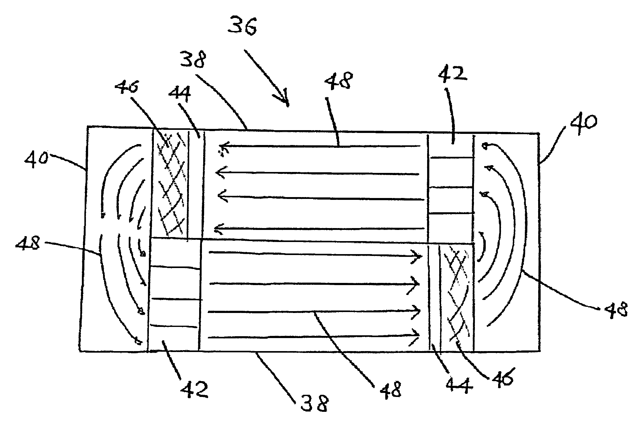
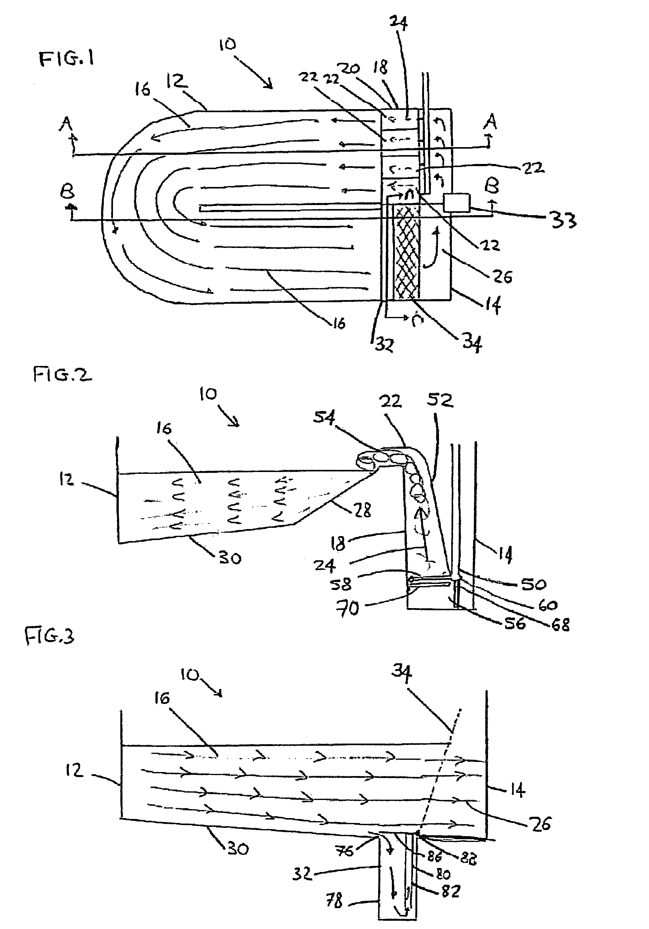
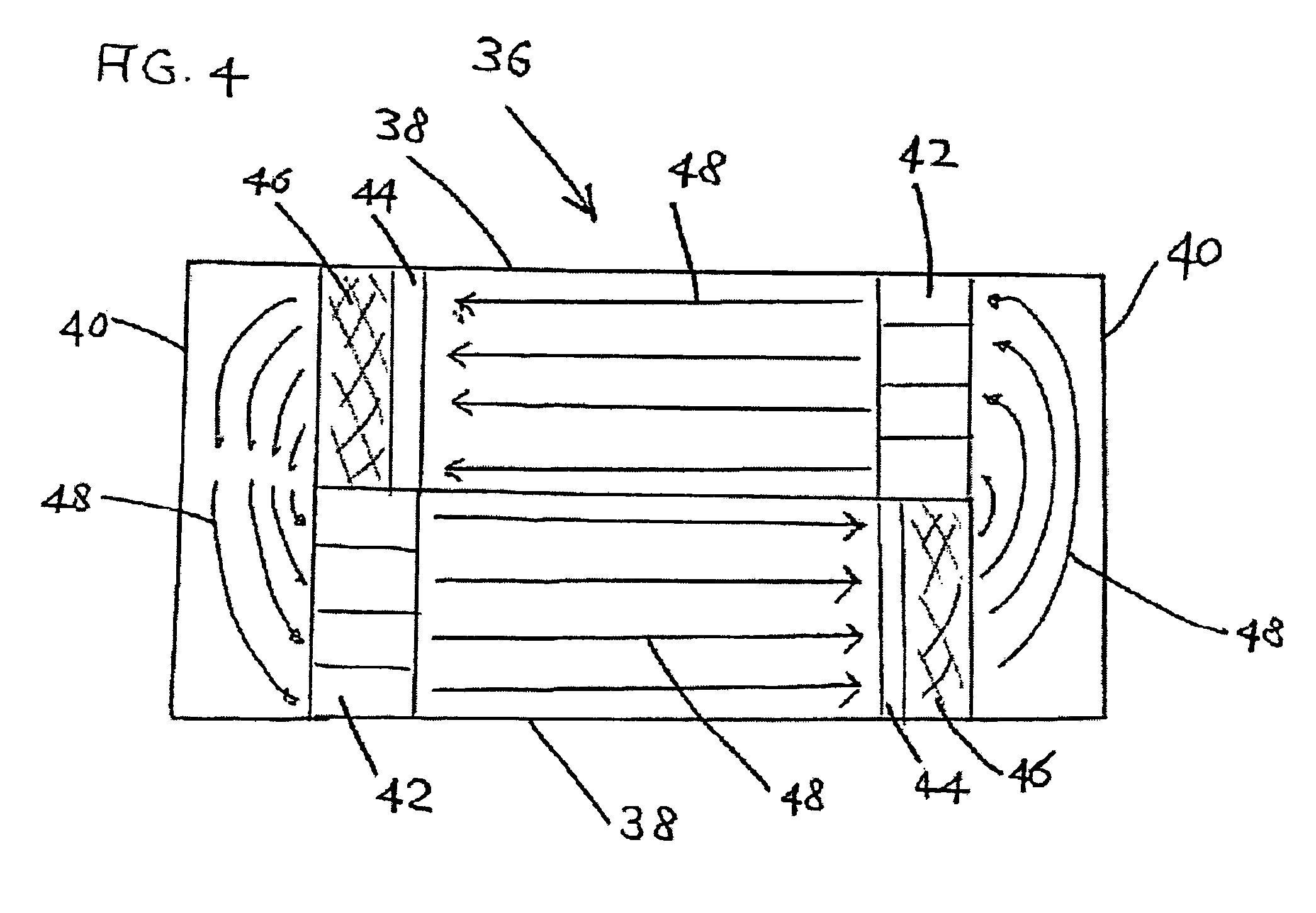
[0056]Reference is now made to FIGS. 1, 2 and 3. FIG. 1 is a plan view of an aerated recirculated aquaculture system 10 that is constructed and operable in accordance with a preferred embodiment of the present invention. FIG. 2 is a cross-section view of aerated recirculated aquaculture system 10 of FIG. 1 through line A-A. FIG. 3 is a cross-sectional view of aerated recirculated aquaculture system 10 of FIG. 1 through line B-B. Aerated recirculated aquaculture system 10 includes a culture tank 12 for housing aquaculture species, for example, fish and shellfish and an aeration tank 14. Culture tank 12 defines a flow path 16. Aeration tank 14 includes an aeration an...


PUM


Abstract

An aerated recirculated aquaculture system including a culture tank and an aeration and circulation system. The culture tank houses live aquaculture. The culture tank defines a first flow path. The aeration and circulation system includes an aeration device configured to aerate water. The aeration device defines a second flow path. The first flow path and second flow path at least partially defining a substantially closed flow path sequentially passing through the culture tank and the aeration device. The aeration and circulation system is configured to circulate the water around the substantially closed flow path.

Description

[0001]This application is a continuation-in-part of PCT Application Number IL03 / 00112 filed Feb. 13, 2003, now WO 03 / 067,966 which in turn claims priority from U.S. Provisional Application No. 60 / 359,451 filed Feb. 15, 2002.FIELD AND BACKGROUND OF THE INVENTION[0002]The present invention relates to an aquaculture system and, in particular, it concerns a system for increasing aquaculture biomass density by aeration using atmospheric air only.[0003]By way of introduction, modem aquaculture is trying to reduce cost of operation and investment in intensive aquaculture facilities by reducing the size of the farm facilities. This is being achieved by creating a relatively small culture volume in which the reared species is cultured at high densities. Such high densities are not common in the natural environment and special means are needed to support the need for dissolved oxygen, degassing of carbon dioxide and removal of solids from the culture water.[0004]The most wide spread solution ...

Claims


Application Information

Patent Timeline
Patent Type & Authority Patents(United States)
IPC IPC(8): A01K63/04A01K
CPCA01K63/00A01K63/04A01K63/042
Inventor HADDAS, ISRAEL
Owner HADDAS ISRAEL
Why Eureka
Try Eureka