Antenna vibration isolation mounting system

a technology of vibration isolation and mounting system, which is applied in the direction of wind-induced force reduction, vessel construction, transportation and packaging, etc., can solve the problems of significant loss of tracking range, vibration, and increase the difficulty of both positioning the antenna and providing a long-term durable antenna, so as to improve the pointing performance of the antenna

Active Publication Date: 2008-06-03
THE BOEING CO
View PDF2 Cites 18 Cited by
  • Summary
  • Abstract
  • Description
  • Claims
  • Application Information

AI Technical Summary

Benefits of technology

[0010]An embodiment of the invention is a vibration isolation system for a maritime antenna assembly which is space stabilized to point at a geosynchronous satellite or other suitable location. The vibration isolation system has a staged construction that slidably attaches an antenna to a maritime vessel or other vehicle along up to three independent axes of translation. This staged construction is adapted for preventing the antenna from rotating and thus enhances the pointing performance for the antenna.
[0011]One advantage of the claimed invention is that a vibration isolation system is provided that improves the pointing and tracking accuracy of an antenna mounted to a maritime vessel.
[0012]Another advantage of the claimed invention is that a vibration isolation system is provided that enhances tracking range of antenna under various movement, e.g. ship motion.

Problems solved by technology

It is understood that the high degree of pointing accuracy increases the difficulty in both positioning the antenna and providing a long-term durable antenna.
Referring now to FIG. 3, ship motion can cause antenna deflection and thus increase stabilization requirements for correcting the deflection or otherwise prevent the antenna from tracking a satellite under predetermined ship motions.
In addition, vibrations are also affected by sea conditions, vessel maneuvering, and vessel loading.
However, the ship motion can cause the springs 18 to have substantially large deflections thereby requiring a significantly sized radome 24 and also producing a significant loss of tracking range.
The rotational torque typically rotates the antenna 14 and thus adversely affects the pointing accuracy of the antenna 14.
This leads to larger motors, increased heat, higher cost, larger weight, increased power consumption and generally shortened life for antenna assembly drive components.

Method used


Image

  • Antenna vibration isolation mounting system
  • Antenna vibration isolation mounting system
  • Antenna vibration isolation mounting system

Examples


Embodiment Construction

[0031]In the following figures, the same reference numerals are used to identify the same or similar components in the various representative views.

[0032]The present invention is particularly suited for a vibration isolation system for use in mounting a satellite antenna to a vehicle in motion, such as a maritime vessel on the high seas. In this regard, the embodiments described herein employ features where the context permits, e.g. when a specific result or advantage of the claimed invention is desired. However, it is contemplated that the vibration isolation system can instead be utilized for attaching various other objects to other vehicles, buildings, or other suitable structures. To that end, a variety of other embodiments are contemplated having different combinations of the described features, having features other than those described herein, or even lacking one or more of those features.

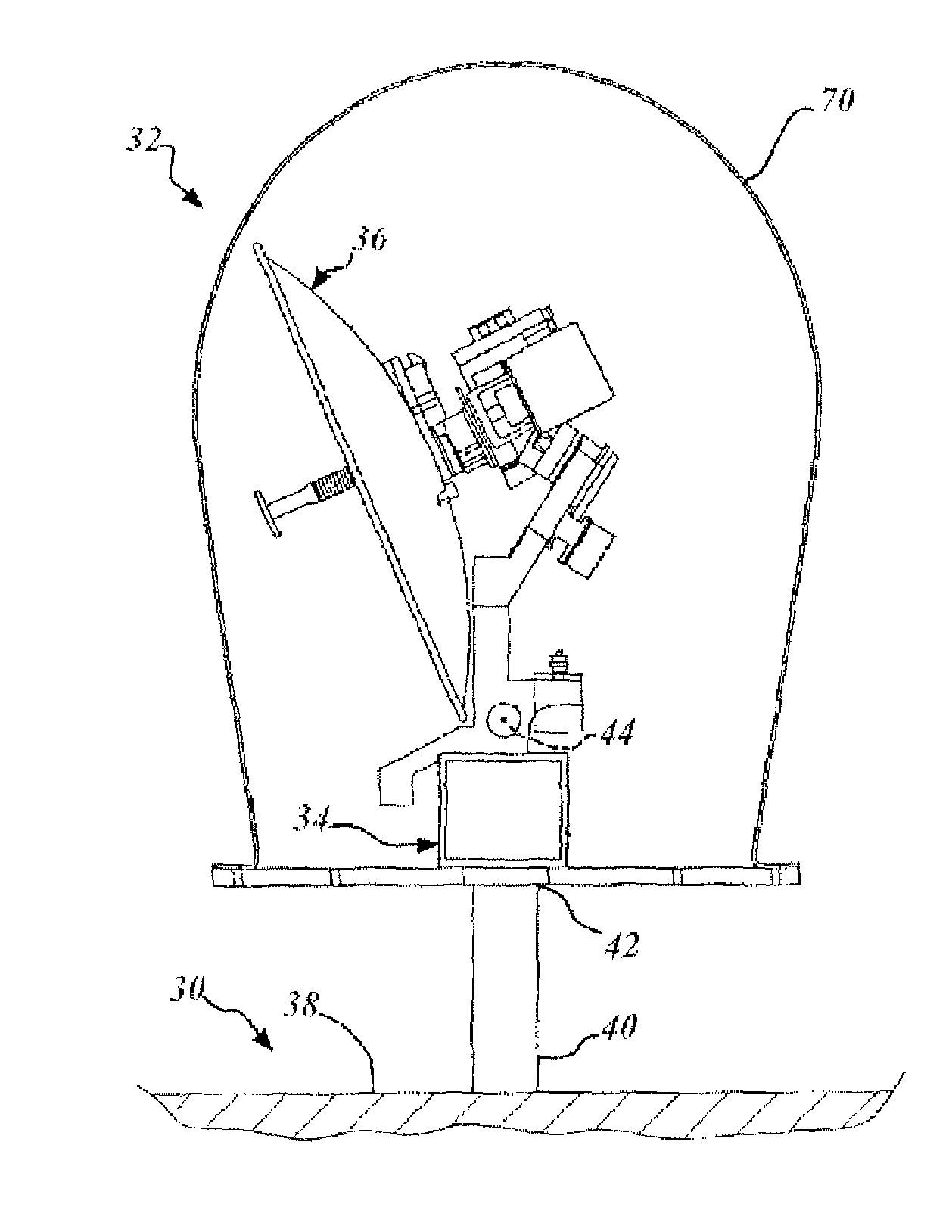
[0033]Referring to FIG. 9, there is shown a maritime vessel 30 having an antenna assembl...


PUM


Abstract

A vibration isolation system for the antenna of a vehicle, such as a maritime vessel. The vibration isolation system has a staged construction that slidably attaches the maritime antenna to a maritime vessel along up to three independent axes of translation. This staged construction is adapted for independently decreasing movement of the antenna along the independent axes of translation. Accordingly, the staged construction prevents the antenna from rotating due to induced translational vibration and thus enhances the pointing performance for the antenna.

Description

FIELD OF THE INVENTION[0001]The present invention relates generally to vibration isolation systems for mounting antenna assemblies to moving vehicles, such as maritime vessels.BACKGROUND[0002]Satellite antenna manufacturers are investigating high-frequency broadband satellite services for maritime vessels. In particular, spectrum in Ku Band and Ka Band is substantially broad and predominantly unused so as to provide an opportunity for economic broadband service.[0003]High-frequency satellite transmissions typically increase the directivity of the satellite antenna. In this regard, the high-frequency transmissions typically can be received by the antenna only when the antenna is accurately pointed at the satellite. It is understood that the high degree of pointing accuracy increases the difficulty in both positioning the antenna and providing a long-term durable antenna. Namely, existing antenna, such as those on a vessel, receive vibrations that can sufficiently perturb the pointing...

Claims


Application Information

Patent Timeline
Patent Type & Authority Patents(United States)
IPC IPC(8): H01Q1/34H01Q1/12H01Q1/42
CPCB63B17/0081H01Q1/005H01Q1/18H01Q1/34H01Q1/42H01Q19/13
Inventor NELSON, LARRY A.
Owner THE BOEING CO
Why Eureka
Try Eureka