Charge pump circuit

Active Publication Date: 2008-06-03
QUINTIC MICROELECTRONICS WUXI
View PDF3 Cites 27 Cited by
  • Summary
  • Abstract
  • Description
  • Claims
  • Application Information

AI Technical Summary

Benefits of technology

[0008]In one embodiment, a charge pump circuit is provided for use in a phase-lock loop circuit. The charge pump circuit comprises a charge pump core circuit that outputs a control voltage. The charge pump circuit also comprises a replica circuit that is coupled to the charge pump core circuit, wherein the replica circuit receives the control voltage and produces one or more bias signals that are coupled to the charge pump core circuit to minimize the difference between charge up and charge down currents generated by the charge pump core circuit.
[0009]In one embodiment, a method is provided for operating a charge pump circuit in a phase-lock loop circuit. The method comprises generating an output control voltage at a charge pump core

Problems solved by technology

Its operation depends on the circuits that comprise the system; and as such, variations in circuit parame

Method used


Image

  • Charge pump circuit
  • Charge pump circuit
  • Charge pump circuit

Examples


Example

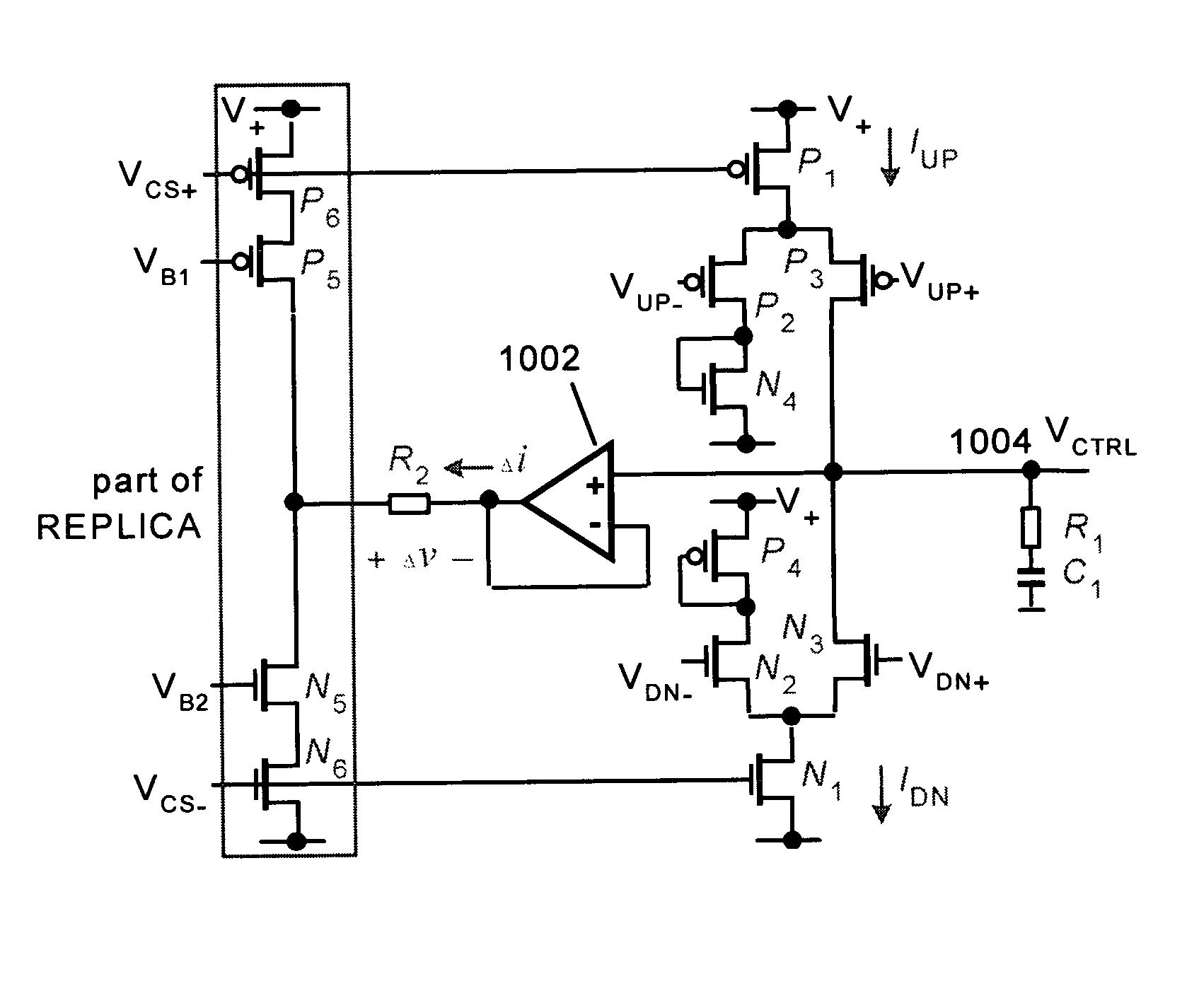
[0027]In one or more embodiments, a PLL system is provided that includes an improved charge pump (CP) circuit that operates linearly and compensates for parameter variations.

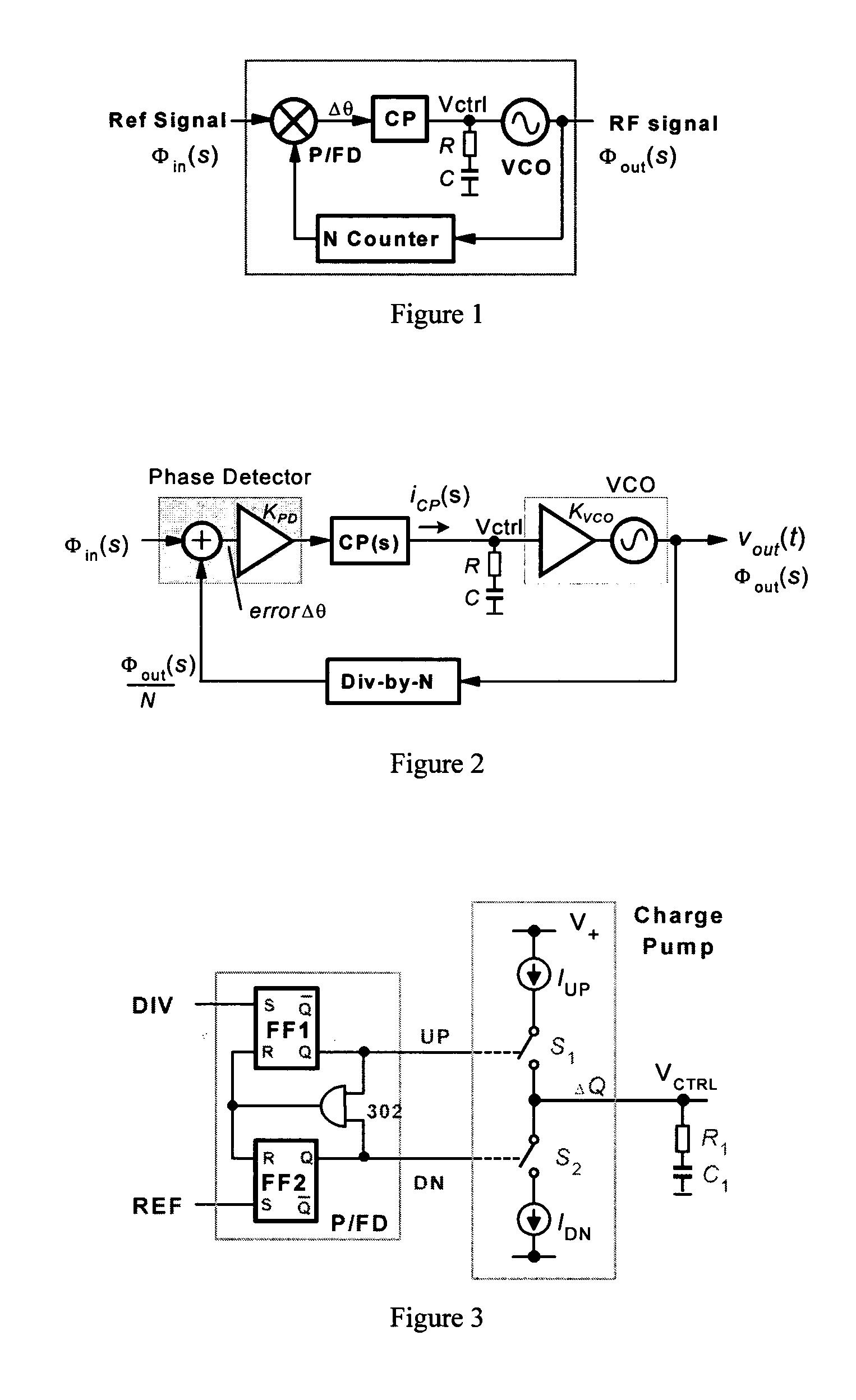
[0028]FIG. 1 shows one embodiment of a PLL that comprises a charge pump (CP), RC integration filter, voltage-controlled oscillator (VCO), N-counter, and a phase / frequency detector (P / FD). The PLL relies on feedback to drive the frequency difference and phase offset between a reference (Ref) signal and the output of the N-counter towards zero. The operation of the PLL may also depend on the circuits that comprise the system; and as such, variations in circuit parameters alter the response of the system, lower the stability of the feedback loop, and introduce distortion. The CP and RC integration filter are circuits that may be especially sensitive.

[0029]FIG. 2 shows a mathematical model of the PLL of FIG. 1. The VCO produces an output signal (Vout) at a frequency set by control voltage (vctrl) that is expressed a...


PUM


Abstract

Charge pump circuit. A charge pump circuit is provided for use in a phase-lock loop circuit. The charge pump circuit comprises a charge pump core circuit that outputs a control voltage. The charge pump circuit also comprises a replica circuit that is coupled to the charge pump core circuit, wherein the replica circuit receives the control voltage and produces one or more bias signals that are coupled to the charge pump core circuit to minimize the difference between charge up and charge down currents generated by the charge pump core circuit.

Description

CROSS REFERENCE TO RELATED APPLICATIONS[0001]This application claims the benefit of priority from a pending U.S. Provisional Patent Application entitled “IMPROVED CHARGE PUMP CIRCUIT” Ser. No. 60 / 405,669 filed on Aug. 24, 2002, the disclosure of which is incorporated by reference herein in its entirety for all purposes.FIELD OF THE INVENTION[0002]The present invention relates generally to phase-locked loop systems, and more particularly, to phase-locked loop systems that utilize charge pump circuits.BACKGROUND OF THE INVENTION[0003]Phase-locked loops (PLL) find widespread use in frequency synthesizers, clock recovery circuits, phase modulators, and frequency demodulators. Generally, a PLL consists of a voltage-controlled oscillator (VCO), counter, phase / frequency detector (P / FD), charge pump (CP), and RC integration filter.[0004]The phase-locked loop relies on feedback to drive the frequency difference and phase offset between a reference signal and the output of the counter towards...

Claims


Application Information

Patent Timeline
IPC IPC(8): H03D3/24
CPCH03L7/0896
Inventor GROE, JOHN B.AUSTIN, JOSEPH
Owner QUINTIC MICROELECTRONICS WUXI
Why Eureka
Try Eureka