Sound reproduction device and portable terminal apparatus

a portable terminal and sound reproduction technology, applied in the direction of diaphragm construction, transducer casing/cabinet/support, electrical transducer, etc., can solve the problems of reducing the pressure level of low-frequency sound to be reproduced, reducing the acoustic compliance of the space, and achieving the effect of improving the sound reproduction capability

Active Publication Date: 2008-06-03
PANASONIC CORP
View PDF5 Cites 53 Cited by
  • Summary
  • Abstract
  • Description
  • Claims
  • Application Information

AI Technical Summary

Benefits of technology

[0012]Therefore, an object of the present invention is to provide a sound reproduction device having an improved sound reproduction capability by adding a sound reproduction capability to a device having a capability other than the sound reproduction capability.

Problems solved by technology

However, a diaphragm formed by the three elements integrated together is heavy in weight, resulting in reduction of a pressure level of sound to be reproduced.
Moreover, an integral structure of the three elements increases the stiffness of the diaphragm, and therefore the diaphragm has difficulty in vibrating at low frequencies, resulting in reduction of low-frequency sound pressure levels.
Accordingly, an acoustic compliance of the space is considerably small, making it difficult for the display device 10 to perform satisfactory low-frequency sound reproduction.
As described above, conventionally, in the case where a display device and a sound reproduction device are integrated together, the sound reproduction device has difficulty in performing satisfactory sound reproduction (in particular, satisfactory low-frequency sound reproduction).
This is not restricted to the display device, and a similar problem can be caused to a device having a different capability if a sound reproduction capability is additionally added thereto.

Method used


Image

  • Sound reproduction device and portable terminal apparatus
  • Sound reproduction device and portable terminal apparatus
  • Sound reproduction device and portable terminal apparatus

Examples


first embodiment

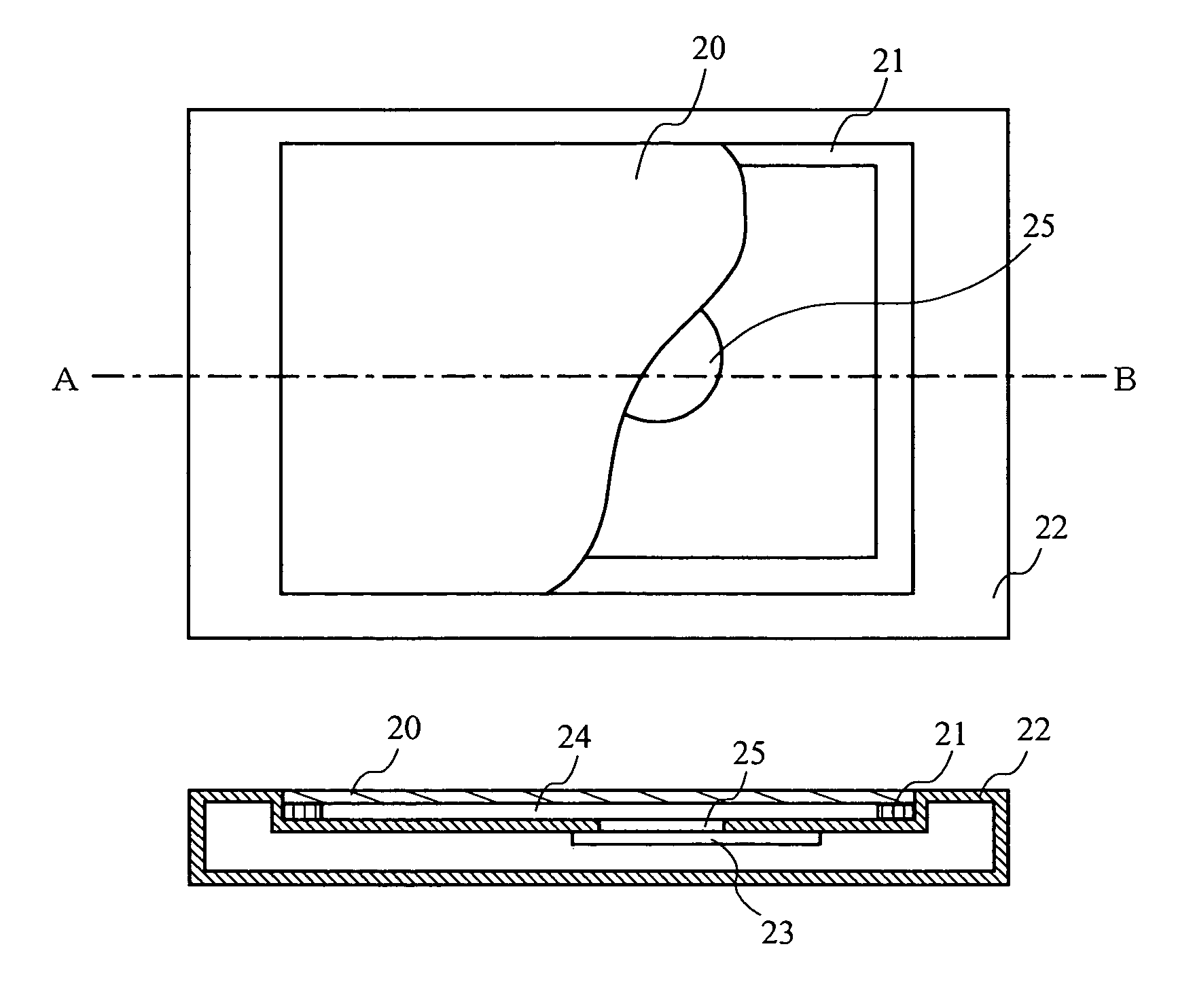
[0051]A sound reproduction device according to a first embodiment of the present invention is described below. FIGS. 1A and 1B each illustrate the sound reproduction device according to the first embodiment. Specifically, FIG. 1A is a plan view of the sound reproduction device shown partially broken away, and FIG. 1B is a cross-sectional view of the sound reproduction device taken along line A-B of FIG. 1A. In FIG. 1A, the sound reproduction device includes a liquid crystal display (LCD) 20, a suspension member 21, a case 22, and an electromechanical acoustic transducer 23. In the first embodiment, as shown in FIG. 1B, the LCD 20, which is an exemplary image display panel for displaying an image, is used as a front panel from which sound is emitted. Note that in FIG. 1A, the LCD20 is shown partially broken away. The sound reproduction device includes an electronic circuit for controlling an image signal supplied to the LCD 20 and an electronic circuit for controlling an acoustic sig...

second embodiment

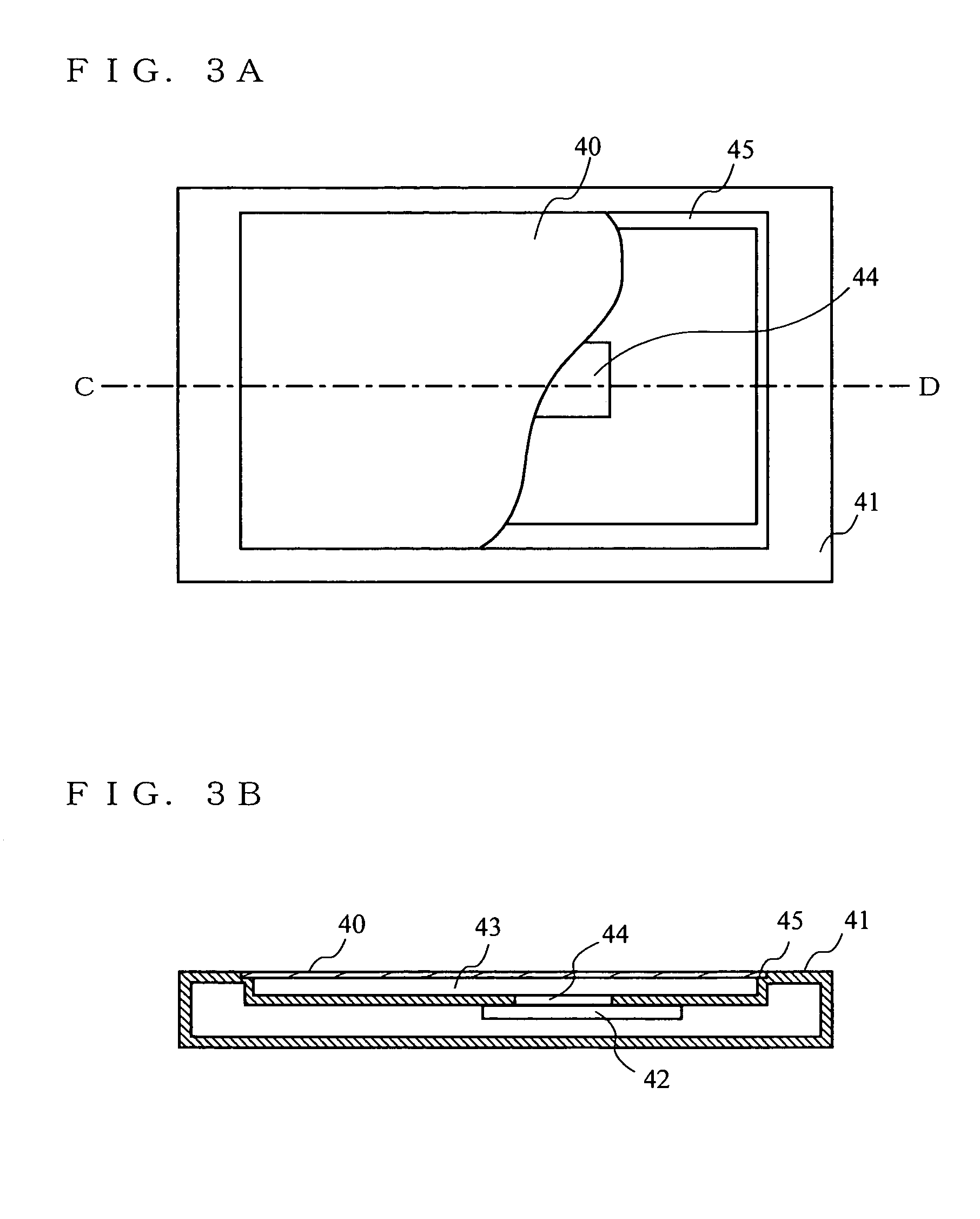
[0059]A sound reproduction device according to a second embodiment is described below. FIGS. 3A and 3B each illustrate the sound reproduction device according to the second embodiment. Specifically, FIG. 3A is a plan view of the sound reproduction device shown partially broken away, and FIG. 3B is a cross-sectional view of the sound reproduction device taken along line C-D of FIG. 3A. In FIGS. 3A and 3B, the sound reproduction device includes a film-like organic electroluminescent (EL) panel 40, a case 41, and an electromechanical acoustic transducer 42. In the second embodiment, as shown in FIG. 3B, the organic EL panel 40 is used as a front panel for emitting sound. Note that in FIG. 3A, the organic EL panel 40 is shown partially broken away.

[0060]The sound reproduction device shown in FIG. 3A differs from the sound reproduction device according to the first embodiment in that instead of using the LCD 20, the film-like organic EL panel 40 is used as a front panel. In FIG. 3A and 3...

third embodiment

[0065]A sound reproduction device according to a third embodiment is described below. FIGS. 4A and 4B each illustrate the sound reproduction device according to the third embodiment. Specifically, FIG. 4A is a plan view of the sound reproduction device, and FIG. 4B is a cross-sectional view of the sound reproduction device taken along line E-F of FIG. 4A. In FIGS. 4A and 4B, the sound reproduction device includes a case 50, a film-like transparent diaphragm 51, transparent electrodes 52, an LCD 53, an electromechanical acoustic transducer 54, and an acoustic tube 55. In the third embodiment, a loudspeaker is used as a front panel. The LCD 53, which is a display device, is provided behind the loudspeaker.

[0066]The transparent diaphragm 51 is composed of a piezoelectric element such as a polymeric piezoelectric sheet material. The transparent electrodes 52 are bonded to opposite surfaces of the transparent diaphragm 51. The transparent diaphragm 51 and the transparent electrodes 52 fo...


PUM


Abstract

A sound reproduction device includes an LCD 20, which is an exemplary front panel, a case 22, and an electromechanical acoustic transducer 23. The LCD 20 is operable to perform a predetermined operation in response to an electrical signal applied thereto. A space 24 for sound emission is formed between the case 22 and the LCD 20. The electromechanical acoustic transducer 23 is connected to the case 22, and emits sound to the space 24. If the electromechanical acoustic transducer 23 emits the sound to the space 24, energy of the emitted sound causes the LCD 20 to vibrate and thereby to externally output the sound.

Description

BACKGROUND OF THE INVENTION[0001]1. Field of the Invention[0002]The present invention relates to a sound reproduction device and a portable terminal apparatus including the acoustic reproduction device. More particularly, the present invention relates to a sound reproduction device having a capability of acoustically driving a panel with sound pressure, and a portable terminal apparatus including the same acoustic reproduction device.[0003]2. Description of the Background Art[0004]Conventionally, it is considered to be important to reduce dimensions or thickness of an electronic apparatus, in particular, a portable apparatus. For example, it is conceivable to integrate two devices in an electronic apparatus, which differ in their functions, into one device, and thereby to reduce the entire size of the apparatus. Described next is a case where a sound reproduction capability is added to an apparatus having a specific capability in order to achieve a size reduction, typically a case w...

Claims


Application Information

Patent Timeline
Patent Type & Authority Patents(United States)
IPC IPC(8): H04R25/00H04M1/02H04B1/38H04R7/04
CPCH04R7/04H04R2499/11H04R1/2834H04R3/14H04R2499/15H04B1/38H04M1/02
Inventor SAIKI, SHUJIUSUKI, SAWAKO
Owner PANASONIC CORP
Why Eureka
Try Eureka