
Processor employing loadable configuration parameters to reduce or eliminate setup and pipeline delays in a pipeline system

Active Publication Date: 2008-06-03
UNIV OF WASHINGTON
View PDF3 Cites 12 Cited by
  • Summary
  • Abstract
  • Description
  • Claims
  • Application Information

AI Technical Summary

Benefits of technology

[0009]The present invention has been developed to address the problems noted above. One aspect of this invention is directed to a pipeline system that includes a host used to control the processing of tasks and to supply configuration parameters employed in processing the tasks by the pipeline. This pipeline system also includes a plurality of configuration register sets in which configuration parameters are selectively loaded by the host. A plurality of stages use the configuration parameters from the configuration register sets to execute the tasks. Also provided are a plurality of control signal sources that track timing events in the pipeline system, producing a plurality of signals that dynamically control access to the plurality of configuration register sets by both the host and the plurality of stages. The configuration registers are setup by the host without delaying processing of the tasks. In addition, the processing of the tasks overlap within the plurality of stages, resulting in a substantial reduction of both a setup delay and a pipeline delay in the pipeline system, as the tasks are processed.
[0015]Another aspect of the present invention is directed to a method for substantially reducing both a setup time and a pipeline delay time for processing tasks in a deep-pipelined architecture. The method includes steps that are generally consistent with the functions of the components of the pipeline system described above. Still another aspect of the present invention is directed to a memory medium that stores machine instructions for carrying out the steps of the method.

Problems solved by technology

Since a pipeline delay (100 cycles in these examples) was added to each run, the pipeline overhead becomes increasingly significant as the size of rectangles decreases.

Method used


Image

  • Processor employing loadable configuration parameters to reduce or eliminate setup and pipeline delays in a pipeline system
  • Processor employing loadable configuration parameters to reduce or eliminate setup and pipeline delays in a pipeline system
  • Processor employing loadable configuration parameters to reduce or eliminate setup and pipeline delays in a pipeline system

Examples


case 1

ne Active Time is Greater Than or Equal to the Pipeline Delay

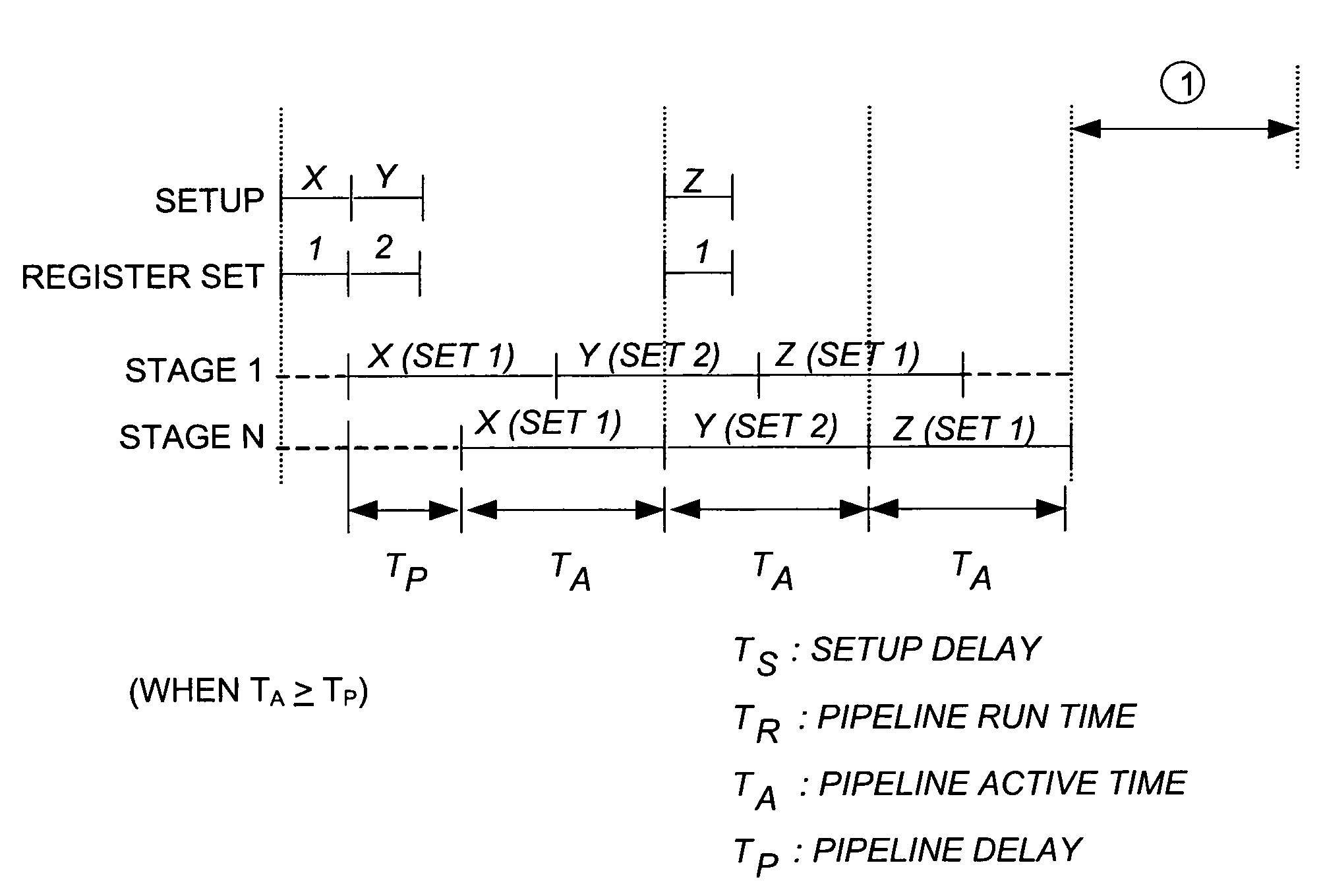
[0045]In the timing example shown in FIG. 4A, which again illustrates the problems of the prior art that were discussed above in regard to FIG. 2B, two sets of configuration registers are used to reduce the overhead of the setup delay. In this example, configuration register set 1 is loaded with the configuration parameters for a Task X during an initial setup time TS, and while Task X is processed using the configuration parameters in configuration register set 1, configuration register set 2 is loaded with the configuration parameters for a Task Y. Following a pipeline delay, TP, configuration register set 1 is loaded with the configuration parameters for Task Z while Task Y is active using the configuration parameters from configuration register set 2. In this example, two consecutive runs do not overlap, because all pipeline stages 1 through N use the same configuration register set.

[0046]To improve the performance of ...

case 2

tive Time is Less Than the Pipeline Delay Time

[0048]Even though two configuration registers sets are used and are dynamically assigned, an idle time can exist if the active time is less than the pipeline delay ((TAP). FIG. 5A illustrates the timing relationships of the prior art when all stages refer to same configuration register set, so that no run can overlap another run. As illustrated therein, in regard to Stage N, a pipeline delay exists prior to the active time for each Task X, Y, and Z.

[0049]The results when two configuration registers sets are used can be substantially improved, as shown in FIG. 5B. However, an idle time still exists even when two register sets are used, because there is no configuration register set available when the first stage finishes the second run. Thus, an idle time, T1, exists between the active time for processing Task Y, and the active time for processing Task Z. Part of this idle time is required for setup of configuration register set 1 with th...


PUM


Abstract

A deep-pipeline system substantially reduces the overhead of setup delays and pipeline delays by dynamically controlling access of a plurality of configuration register sets by both a host central processing unit (CPU) and the stages of the pipelines. A master configuration register set is loaded with configuration parameters by the host CPU in response to an index count provided by a setup-index counter. A plurality of other counters are employed to track timing events in the system. In one embodiment, a run-index counter provides a run-index count to the first stage of the pipeline that is propagated along the stages, enabling configuration register sets to transfer configuration parameters to the stages of the pipeline when required to enable processing of a task. In an alternative embodiment, a plurality of D flip-flops sequentially propagates a state for successive registers, so that the setup-index counter is not required.

Description

FIELD OF THE INVENTION[0001]The present invention is generally directed to a deep-pipeline system that controls access to sets of configuration registers by a host and stages of the pipeline, and more specifically, pertains to dynamically controlling transferring configuration parameters into configuration register sets from the host and dynamically controlling the access of the configuration register sets by the stages of the pipeline, in response to control signals that indicate a current status of the system, thereby enabling the processing of tasks by the pipeline to proceed without being affected by the overhead of setup and pipeline delays.BACKGROUND OF THE INVENTION[0002]Deep-pipelined architectures are widely employed in application specific integrated circuits (ASICs) and graphics processors. Pipelining is an implementation technique that divides tasks such as rendering a graphic object or implementing wavelet transforms into smaller subtasks that are allocated to a plurali...

Claims


Application Information

Patent Timeline
IPC IPC(8): G06F7/38G06F15/00G06F9/00G06F9/44G06F9/38G06F15/78
CPCG06F9/3851G06F15/8053
Inventor CHUNG, CHRIS Y.MANAGULI, RAVI A.KIM, YONGMIN
Owner UNIV OF WASHINGTON
Learn More