
Method for drying veneers

a drying method and veneer technology, applied in drying machines, drying machines with progressive movements, drying machines, etc., can solve the problems of veneer damage, veneer was subject to checking, veneer was prone to scorching, etc., to improve control and monitoring the drying process.

Inactive Publication Date: 2008-06-10
BASE POINT
View PDF7 Cites 7 Cited by
  • Summary
  • Abstract
  • Description
  • Claims
  • Application Information

AI Technical Summary

Benefits of technology

[0009]The present invention provides a drying apparatus and method for extracting moisture from a piece of veneer by vaporizing or boiling-off the moisture within the veneer through heat exposure at sub-atmospheric pressure, i.e., below standard atmospheric pressure 760 mmHg. In accordance with the method and apparatus for single sheet veneer drying, a piece of veneer is exposed to heat under vacuum. Thus, as a result, the heat-exposed piece of veneer has a uniform surface porosity as will similarly treated pieces of veneer, which can be stained and finished uniformly.
[0011]Sensors and instruments are used to measure the vacuum pressure and temperature within the chamber and the temperature of a piece of veneer, all of which enables improved control and monitoring of the drying process.

Problems solved by technology

However, in accord with the prior art dryer, the veneer was prone to scorching when heated above 270° F. by infrared energy, and the veneer was subject to checking, i.e., cracking in fissures of dry wood, as a result of rapid removal of water from the veneer.
However, the motion created by conveyors moving the veneer through the chamber tends to damage the veneer.
In accord with the more modern dryers, the veneer is still damaged through the use of roller conveyors that squeeze the piece of veneer, which is also subject to damage by conveyor motion.

Method used


Image

  • Method for drying veneers
  • Method for drying veneers
  • Method for drying veneers

Examples


Embodiment Construction

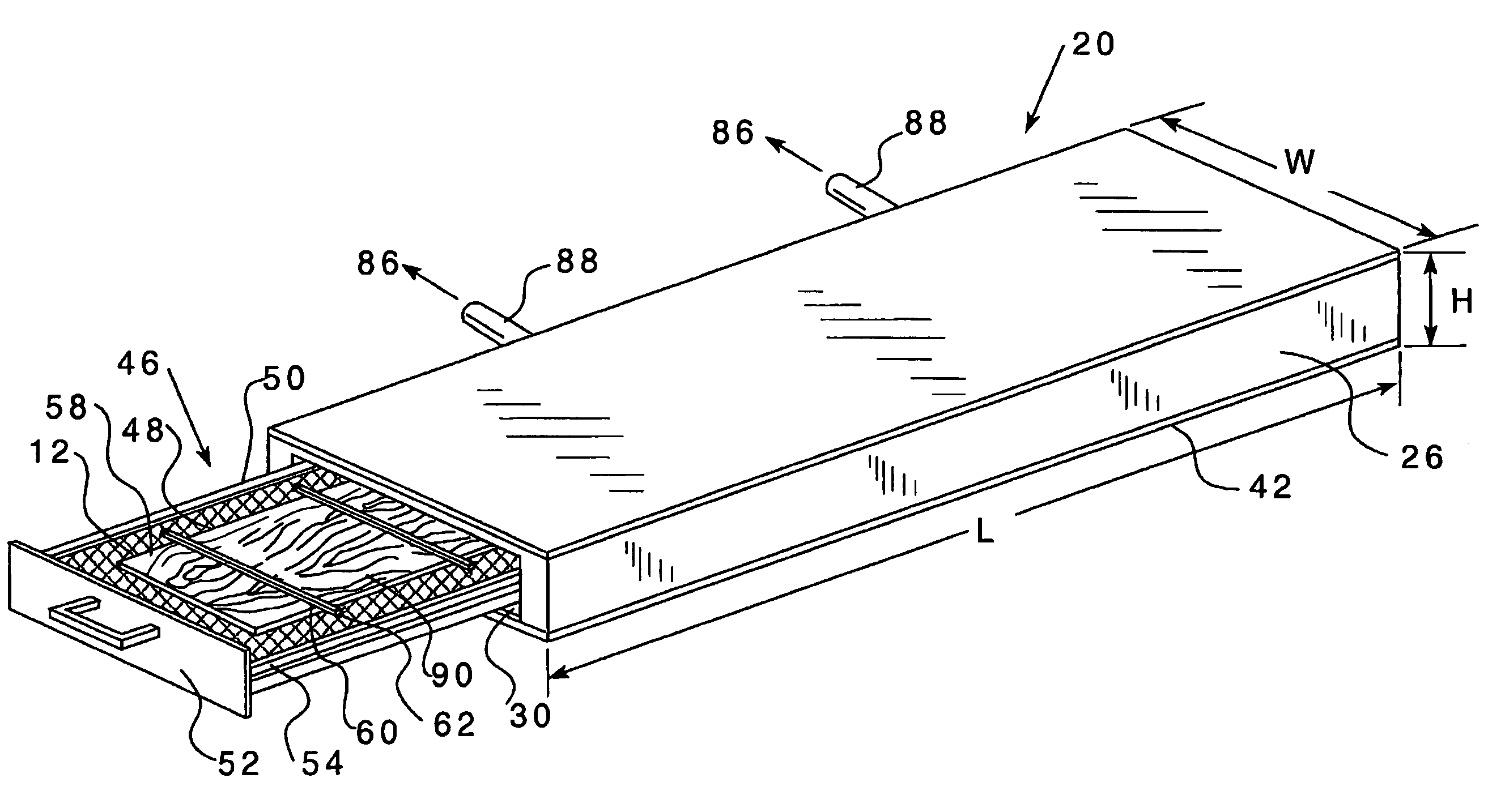
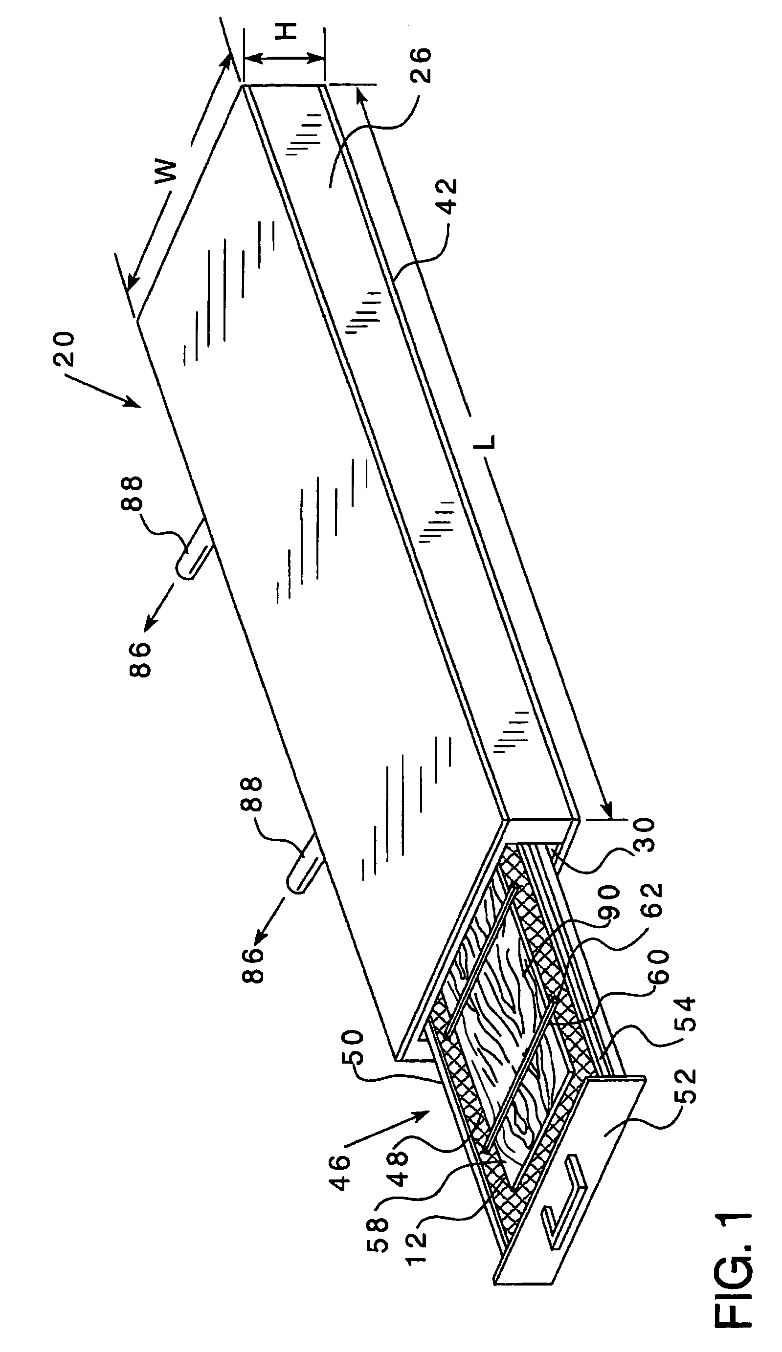
[0023]While this invention is satisfied by embodiments in many different forms, shown in the drawings and herein described in detail are the embodiments of the invention, with the understanding that the present disclosure is to be considered as exemplary of the principles of the invention and is not intended to limit the invention to the embodiments illustrated. Various other modifications will be apparent to and readily made by those skilled in the art without departing from the scope and spirit of the invention. The scope of the invention will be measured by the appended claims and equivalents. In FIGS. 1 through 8, similar reference characters refer to similar parts throughout the several views of a drying apparatus 20 and method of use thereof. The word “item” as used in this disclosure and claims includes pieces of veneer, tobacco, foodstuff or any other item that requires drying prior to use. Additionally, although the word “veneer” is used in the disclosure and the claims as ...


PUM


Abstract

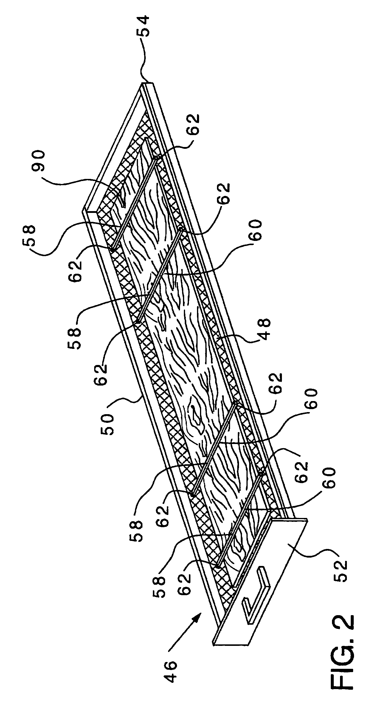
An apparatus and method is provided to dry veneer or other items by vaporization of moisture in the item. Apparatus has an insulated chamber with a frame and a drawer with a door. A mesh surface of the drawer supports item for drying with a heater at sub-atmospheric pressure inside of the chamber. Item is placed on the layer of mesh of the drawer of the apparatus and secured with fasteners such as another layer of mesh. The drawer with fastened item is placed into the chamber of the apparatus. With the drawer fully engaged within the chamber, the drying apparatus is closed with an airtight seal. A pump draws a vacuum in the chamber and heat is directed at the item to raise the temperature of the item to less than 160° F., particularly between 120° F. to 150° F. Apparatus can dry veneer in less than five minutes.

Description

CROSS REFERENCE TO RELATED APPLICATIONS[0001]This application claims the benefit of U.S. Provisional Application No. 60 / 555,884 entitled “Method and Apparatus for Drying Materials Including Veneers” filed Mar. 24, 2004, which is incorporated herein by reference.BACKGROUND OF THE INVENTION[0002]1. Field of the Invention[0003]The present invention relates to an apparatus and method of use thereof for drying materials, such as veneer, including a chamber at sub-atmospheric pressure with an internal heating source.[0004]2. Description of Related Art[0005]Traditional prior art veneer dryers use heat from a variety of sources to dry pieces of veneer or other panel materials moving through the dryers on conveyors at high temperatures and high velocities. For example, U.S. Pat. No. 3,474,544 to Holden Jr., et al. discloses a method and apparatus for changing the moisture content of veneer. By way of a conveyor system, veneer is fed at velocities of 30 to 50 mph through multiple treatment ar...

Claims


Application Information

Patent Timeline
Patent Type & Authority Patents(United States)
IPC IPC(8): F26B5/04F26B9/06F26B13/30
CPCF26B5/045F26B5/048F26B9/066F26B2210/14
Inventor BLANKENSHIP, TIMOTHYHIMES, JUNIUSLILLESAND, BRENTTODD, JAMESCONSTANTINE, EDWARD
Owner BASE POINT
Learn More