Package structure of sensor and flow sensor having the same

a sensor and flow sensor technology, applied in the field of sensor and flow sensor packaging structure, can solve the problems of reducing the strength of the constricted part, affecting the characteristics of the sensor, etc., and achieve the effect of reducing the number of components, reducing the cost, and ensuring sufficient air tightness

Inactive Publication Date: 2008-06-10
YAMATAKE HONEYWELL CO LTD
View PDF7 Cites 15 Cited by
  • Summary
  • Abstract
  • Description
  • Claims
  • Application Information

AI Technical Summary

Benefits of technology

[0010]The sensor chip formed by connecting the lead pattern of the detecting device formed on the front surface of the substrate to the front-surface-side end of the through electrode formed on the substrate is mounted on the conduction path body formed of, e.g., a metal member through the sealing means, thereby sealing the conduction path formed to face the detecting device. Moreover, the pressing member is pressed against the rear surface of the sensor chip to fix the sensor chip to the conduction path body. When the sensor chip is pressed against the conduction path body, the sealing means collapses to be appressed against the sensor chip and the conduction path body, thereby assuring sealing properties of the conduction path. Additionally, a difference in thermal expansion coefficient between the sensor chip and the conduction path body is absorbed, and distortion due to the difference in thermal expansion coefficient is reduced to improve stability of the sensor.
[0022]Further, a signal of the sensor can be fetched from the rear surface of the sensor chip, the structure of the package becomes simple, a cost can be reduced, and assembling properties can be improved. Furthermore, changing a height, a width, and a shape of the flow path formed in the flow path body enables easy adjustment of a flow rate measurement range in accordance with specifications. Moreover, the sensor chip can be attached to / detached from the flow path body, thereby facilitating replacement or maintenance of the sensor chip.

Problems solved by technology

However, when a glass chip is bonded to a flow path body formed of a stainless member through, e.g., brazing, a difference in thermal expansion coefficient between both the members provokes distortion, thereby affecting sensor characteristics.
2, FIG. 1), since a part of a glass chip is constricted to take out an electrode, there is a problem of a reduction in strength of this constricted part.

Method used


Image

  • Package structure of sensor and flow sensor having the same
  • Package structure of sensor and flow sensor having the same
  • Package structure of sensor and flow sensor having the same

Examples


Embodiment Construction

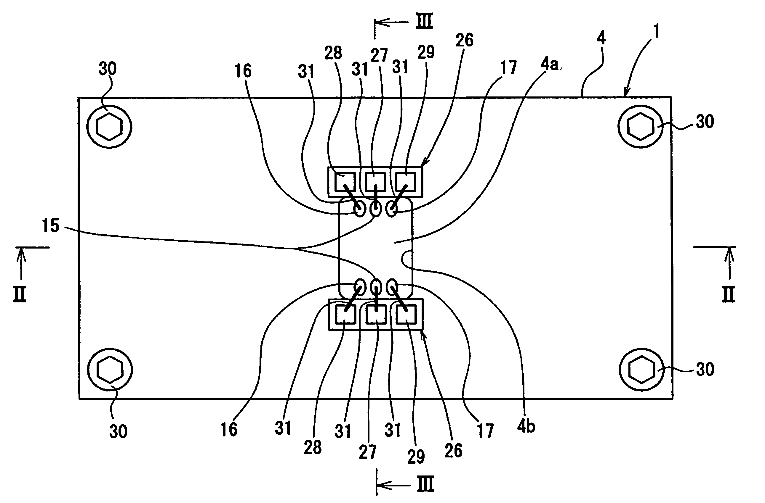
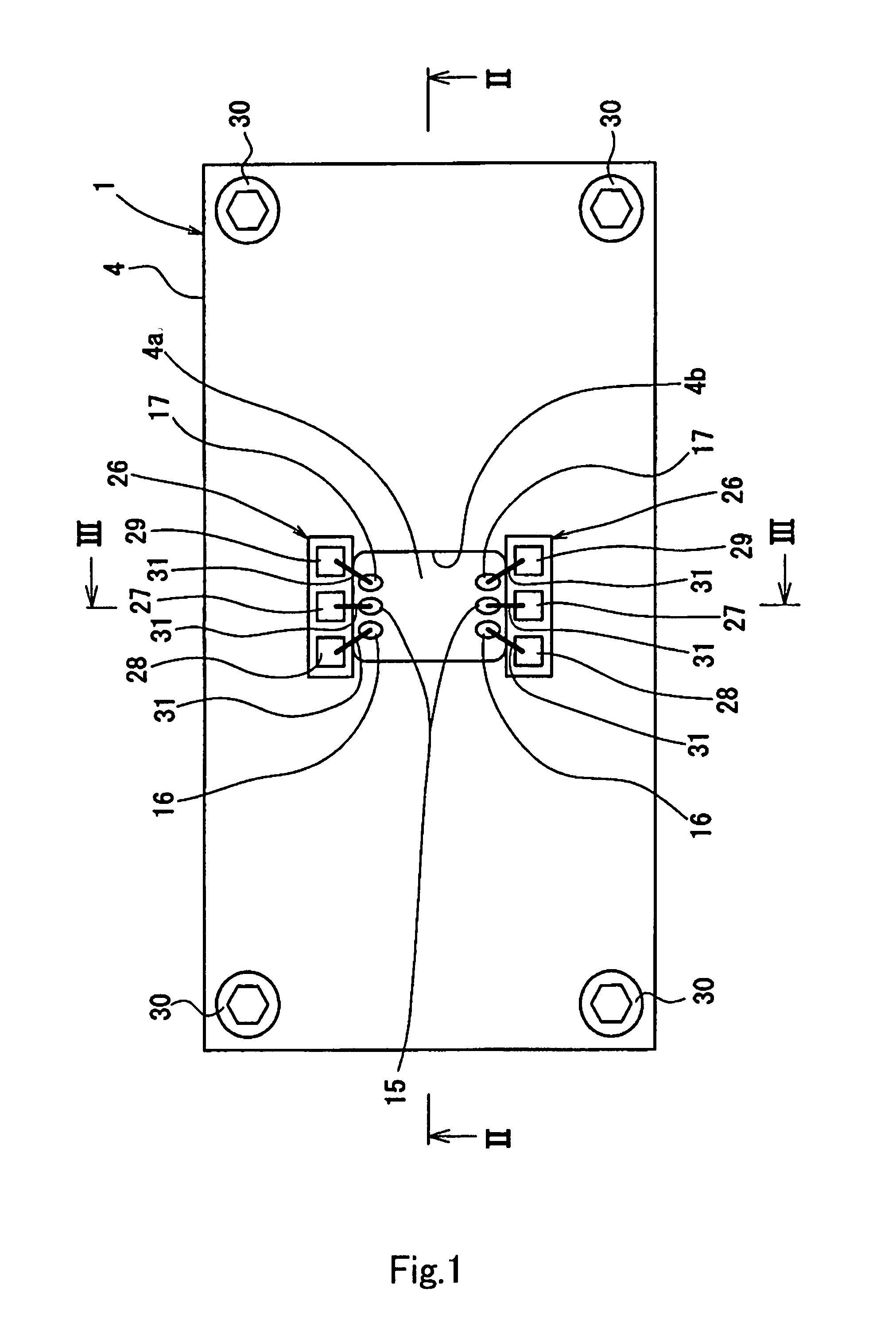
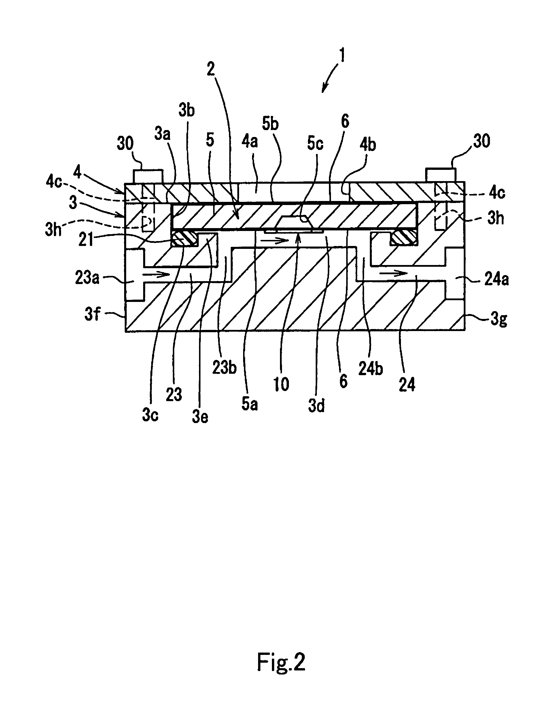
[0029]A package structure of a sensor according to an embodiment of the present invention will now be explained hereinafter with reference to the accompanying drawings. FIG. 1 is a plan view of a flow sensor to which a package structure of a sensor according to the present invention is applied, FIG. 2 is a cross-sectional view of the flow sensor taken along an arrow line II-II depicted in FIG. 1, and FIG. 3 is a cross-sectional view of the flow sensor taken along an arrow line III-III depicted in FIG. 1. As shown in FIGS. 1 to 3, a flow sensor 1 includes a flow sensor chip 2, a flow path body 3 that accommodates this flow sensor chip 2, and a pressing plate 4. For example, the flow sensor 1 is connected with a flowmeter or a flow rate controller, e.g., a mass flowmeter or a mass flow controller of a semiconductor manufacturing apparatus.

[0030]As shown in FIG. 2, in the flow sensor chip 2, a flow rate detecting device 10 is formed at a central position of a silicon nitride or silicon...


PUM


Abstract

The package structure may includes: a sensor chip having a detecting device formed on a front surface of a substrate; through electrodes that are arranged at predetermined positions of the substrate around the detecting device, electrically insulated at circumferences thereof, pierce the substrate from the front surface to a rear surface, are connected with lead patterns of the detecting device on the front surface side, and connected with signal fetching means for the outside on the rear surface side; a flow path body on which the sensor chip is mounted and which has a flow path (a conduction path) for a fluid being formed on a surface facing the detecting device and sealing means.

Description

CROSS REFERENCE TO RELATED APPLICATIONS[0001]The present invention claims priority under 35 U.S.C. §119 to Japanese Application No. 2006-030312 filed Feb. 7, 2006, which is incorporated herein by reference.BACKGROUND OF THE INVENTION[0002]1. Field of the Invention[0003]The present invention relates to a package structure of a sensor that measures a small flow rate, a pressure, a temperature, a concentration, a composition or the like of, e.g., a gas used in a semiconductor manufacturing apparatus, and to a flow sensor having the same.[0004]2. Description of the Related Art[0005]For example, as a flow rate measuring apparatus (a flow sensor) that detects a flow rate of a fluid, e.g., a gas used in a semiconductor manufacturing apparatus, there is a thermal type flow rate measuring apparatus that gives heat to a fluid and measures a temperature difference of the fluid at a predetermined position to measure a flow rate (see, e.g., Japanese Patent Application Laid-open No. H5(1993)-9972...

Claims


Application Information

Patent Timeline
Patent Type & Authority Patents(United States)
IPC IPC(8): G01F1/68
CPCG01F1/6842G01F1/6845G01F1/692
Inventor IKE, SHINICHIZUSHI, NOBUHIKONISHI, TAKESHI
Owner YAMATAKE HONEYWELL CO LTD
Why Eureka
Try Eureka