Floatation module and method

a floating module and floating technology, applied in mechanical equipment, sealing/packing, wellbore/well accessories, etc., can solve the problems of large equipment required to safely drill ultra deep water wells, difficult to safely handle, and heavy design that even now barely meets load requirements, so as to reduce the requirement of rig hoisting.

Active Publication Date: 2008-06-10
VON EBERSTEIN WILLIAM
View PDF26 Cites 33 Cited by
  • Summary
  • Abstract
  • Description
  • Claims
  • Application Information

AI Technical Summary

Benefits of technology

[0016]An advantage of the present invention includes an apparatus and method that safely reduces rig hoisting requirements. Another advantage is that the invention is safer than prior art methods and devices. Yet another advantage is that an operator can install floatation modules before going to the rig site, or can install at the rig site. Another advantage is the modularity of the invention. For instance, an operator can install several floatation modules per joint of pipe, or alternatively, the operator can space out floatation modules in a predetermined sequence along the entire length of the landing string in order to effect the desired amount of buoyancy.
[0017]A feature of the invention is that the buoyancy material, such as syntactic foam, is bonded to a sleeve, such as an aluminum sleeve. Another feature is that the sleeve consist of two cylindrical halves that are latched together to form the floatation module. A feature is the clamp means for clamping the halves together. Yet another feature is that the sleeve can contain engagement means that comprises slots. Another feature is that the clamp means includes dies that engage with the slots thereby holding the sleeves about the landing string.

Problems solved by technology

The equipment required to safely drill ultra deep water wells is large, extremely heavy, and difficult to safely handle.
Numerous problems involving drill pipe slip crushing and catastrophic slip failures have occurred which have required new heavier designs that even now barely meet load requirements.
For instance, some of the problems encountered include: extremely high differential pressures on float equipment; failure of float equipment could cause immediate overloading of rig hoisting system caused by loss of buoyancy, which would be catastrophic; well control and / or stuck pipe due to swabbing or suction if floats fail; casing collapse; and, removal of air in casing effects circulation and cementation of the casing.

Method used


Image

  • Floatation module and method
  • Floatation module and method
  • Floatation module and method

Examples


Embodiment Construction

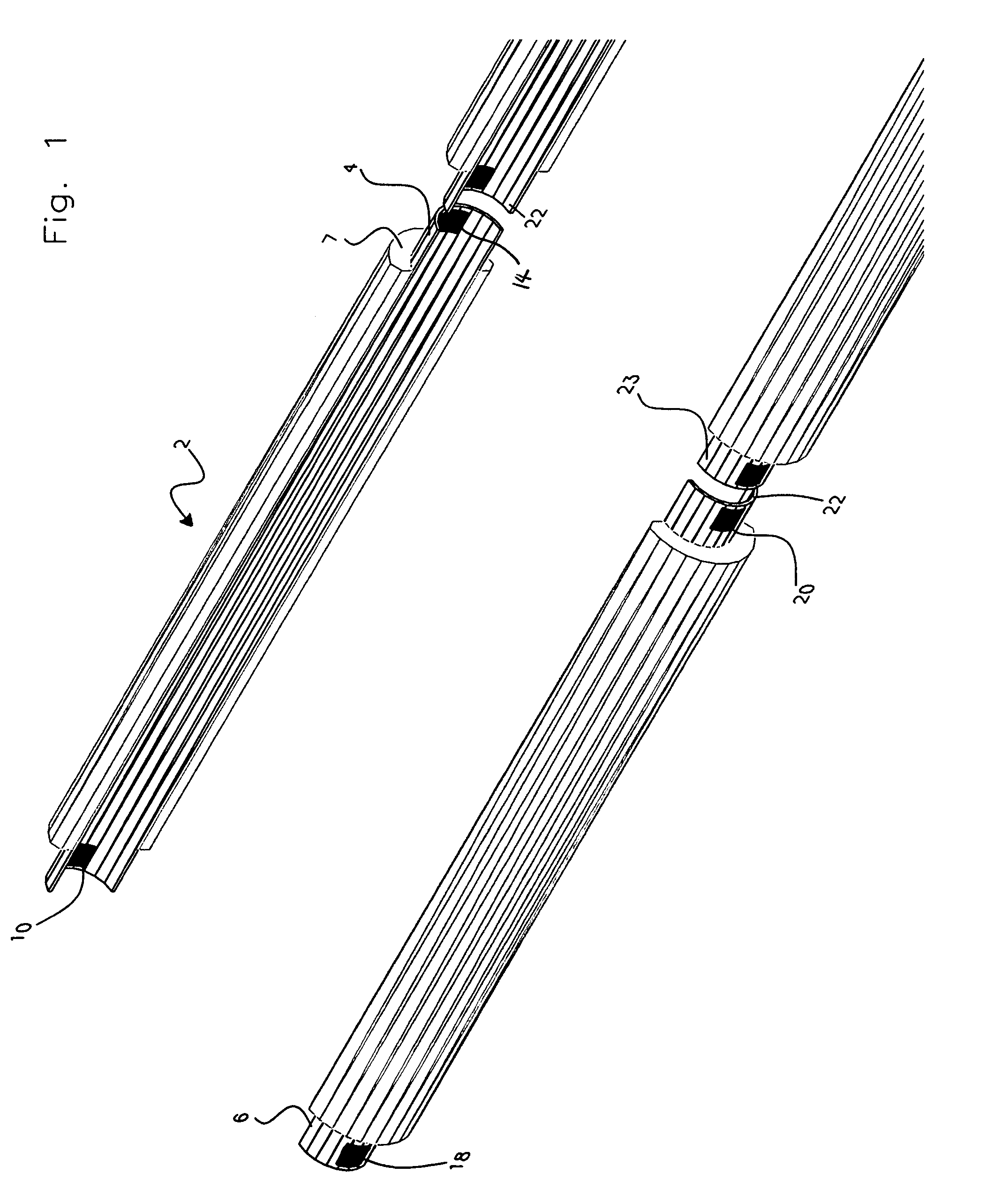
[0025]Referring to FIG. 1, an isometric view of the floatation module 2 of the present invention in the open position will now be described. As seen in FIG. 1, the floatation module 2 contains a first half cylindrical sleeve 4 and a second half cylindrical sleeve 6. A cylindrical member is formed when the first half cylindrical sleeve 4 and second half cylindrical sleeve are joined together. In the most preferred embodiment, the first half tubular sleeve 4 and the second half tubular sleeve 6 are constructed of aluminum.

[0026]A buoyant material will be bonded to the first half cylindrical sleeve 4 and the second half cylindrical sleeve 6. In the most preferred embodiment, the buoyant material is a syntactic foam commercially available from CRP Corporation under the name Syntactic Foam. For instance, the 3 bonded foam, which is bonded to the sleeve 4, is seen generally at 7.

[0027]FIG. 1 also shows that the first half cylindrical sleeve 4 has means for engaging with a clamp, wherein t...


PUM


Abstract

An apparatus for reducing the load applied to a rig. The rig is positioned over a well, with the well having a tubular string disposed therein. A landing string is connected to the tubular string such as casing, production and / or testing assemblies. The apparatus comprises a floatation module attached to the landing string and a clamp for clamping the floatation module onto the landing string. In one embodiment, the floatation module comprises a tubular sleeve having a buoyant material applied thereto. The tubular sleeve includes slots. The clamp may contain a set of dies adapted to engage the slots of the tubular sleeve. A method of landing a work string into a sub-sea well head from a floating drilling rig is also disclosed, wherein a marine riser connects the rig to the sub-sea well head.

Description

BACKGROUND OF THE INVENTION[0001]This invention relates to a floatation module and method of using the floatation module. More particularly, but not by way of limitation, this invention relates to a floatation module and method for safely reducing the rig hoisting requirements to run tubular strings into sub-sea wells and well bores.[0002]As the energy industry continues to search the globe for hydrocarbon reservoirs, the search has increasingly focused in the world's oceans. Economical hydrocarbon reservoirs are increasingly being discovered and developed in deep water tracts located in remote and exotic places on the planet. Floating drilling platforms, such as mobile offshore drilling units (MODU's), are anchored in water depths of more than 9,200 feet and are dynamically positioned in water depths greater than 10,000 feet.[0003]In combination with this deep water drilling, the actual wells drilled are in increasingly deeper water in order to penetrate commercially feasible hydro...

Claims


Application Information

Patent Timeline
Patent Type & Authority Patents(United States)
IPC IPC(8): E21B33/00E21B17/00
CPCE21B17/012E21B17/105
Inventor BERGERON, BILLY JAMESVON EBERSTEIN, WILLIAM
Owner VON EBERSTEIN WILLIAM
Why Eureka
Try Eureka