
Oscillating disc cutter with speed controlling bearings

a technology of speed control bearings and cutting discs, which is applied in the direction of cutting machines, bearings, rotary combination bearings, etc., can solve the problems of increased drag, heavy arrangement, and significant wear and damage of cutting edges, and achieve the effect of limiting the rotational speed of cutting discs

Inactive Publication Date: 2008-06-10
ODYSSEY TECH
View PDF49 Cites 19 Cited by
  • Summary
  • Abstract
  • Description
  • Claims
  • Application Information

AI Technical Summary

Benefits of technology

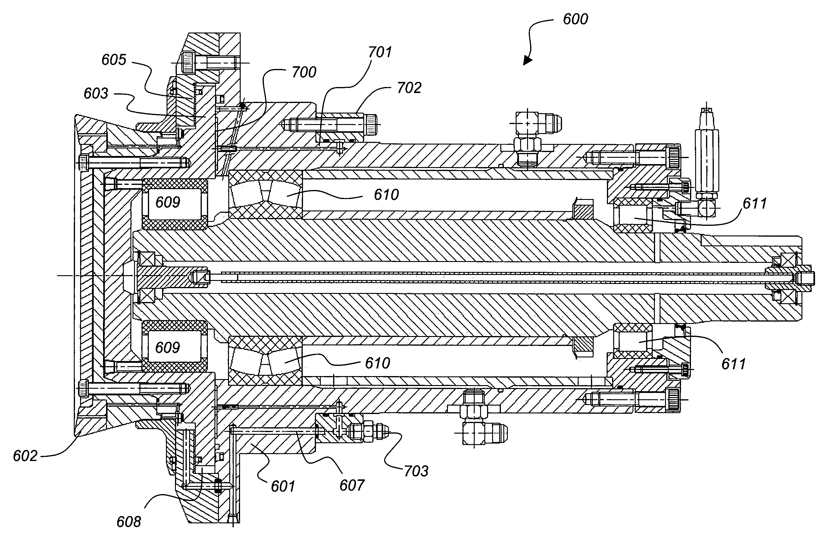
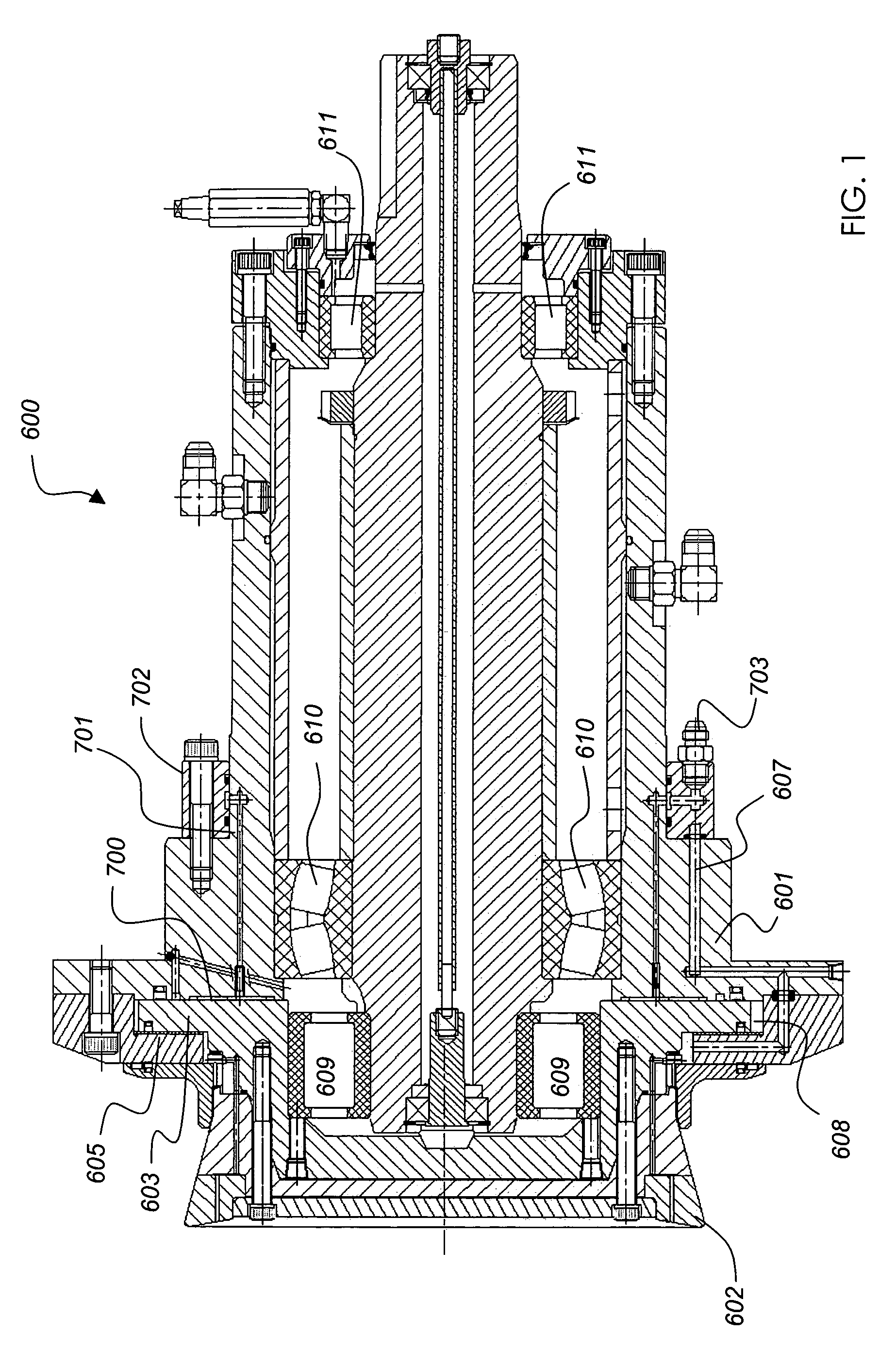
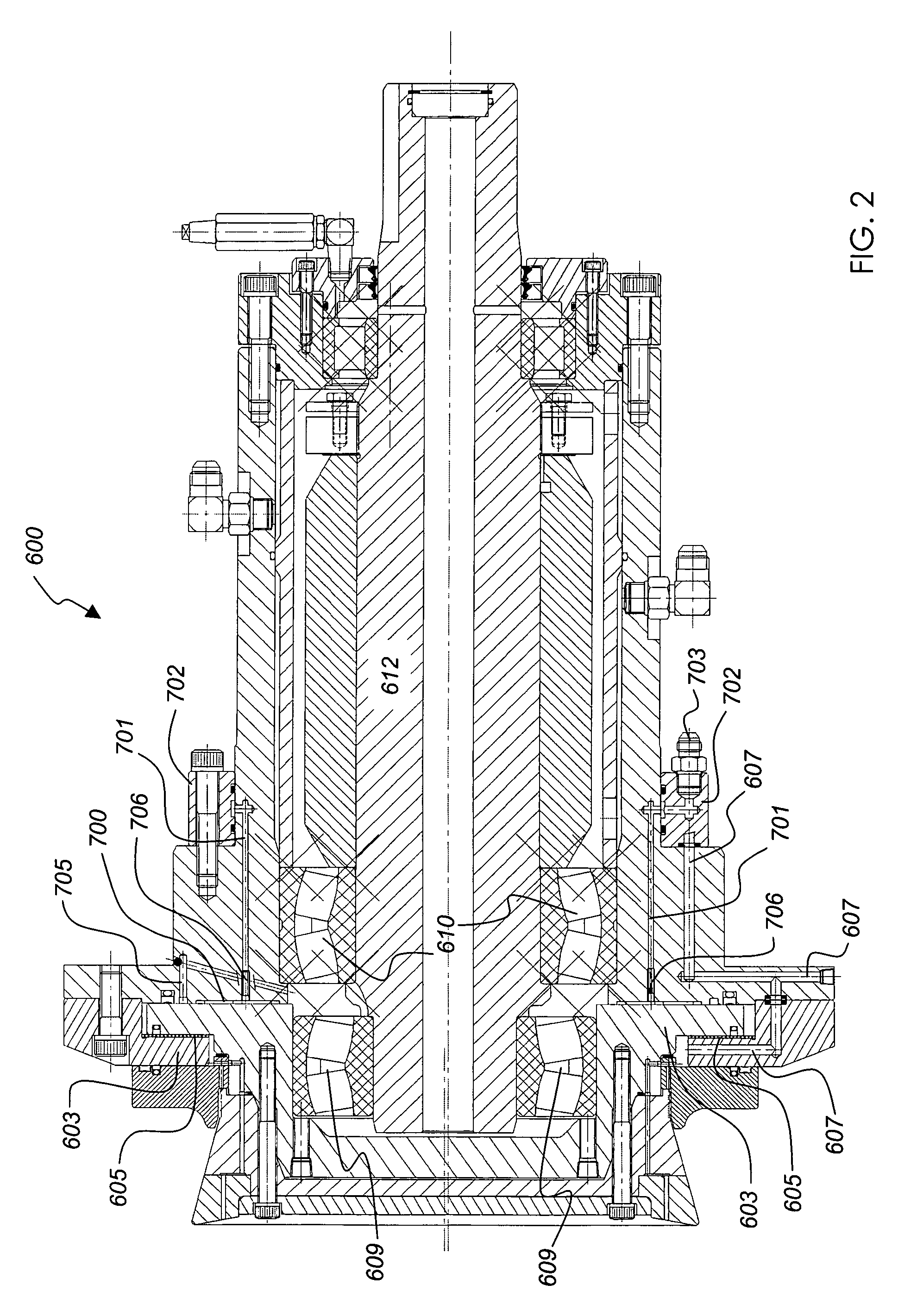
"The present invention provides an oscillating disc cutter with a cutting disc and a drive mechanism that allows for eccentric oscillation of the cutting disc. The cutter also includes a first axial bearing that reacts to axial forces and induces a rotational drag to limit the speed of the cutting disc when free running. A second bearing is added for a specific axial load and substantially reacts to the first bearing. The first bearing is an oil-operated hydrostatic bearing and the second bearing is a fluid pressurised and lubricated bearing. The pressure in the fluid bearing is maintained to induce shear forces in the oil of the hydrostatic bearing, which causes rotational drag and limits the speed of the cutting disc when free running. The limited rotational speed of the cutting disc is 0 to 100 rpm."

Problems solved by technology

This can cause significant wear and damage to the cutting edge.
Such a gear arrangement is heavy, prone to wear, maintenance issues, and causes additional drag when the cutter is engaged with the rock face.

Method used


Image

  • Oscillating disc cutter with speed controlling bearings
  • Oscillating disc cutter with speed controlling bearings
  • Oscillating disc cutter with speed controlling bearings

Examples


Embodiment Construction

[0025]FIG. 4A is a cross-sectional view of an oscillating disc cutting device according to WO 00 / 46486. The cutting device 10 includes a mounting assembly 11 and a rotary disc cutter 12. The mounting assembly 11 includes a mounting shaft 13 which is rotatably mounted within a housing 14, that can constitute or be connected to a large mass for impact absorption. The housing 14 thus, can be formed of heavy metal or can be connected to a heavy metallic mass. The shaft 13 is mounted within the housing 14 by a bearing 15 mounted against a stepped section 16.

[0026]The housing 14 can have any suitable construction, and in one form includes a plurality of metal plates fixed together longitudinally of the shaft 13. Such an arrangement is shown in FIG. 4B, and with this arrangement, applicant has found that a plurality of iron plates 17a and a single lead plate 17b provides effective impact absorption based on weight and cost considerations.

[0027]The shaft 13 is mounted for rotating motion ab...


PUM


Abstract

An oscillating disc cutter including a cutting disc and a drive mechanism. The drive mechanism includes a drive shaft to effect eccentric oscillation of the cutting disc and a radial bearing disposed to permit relative rotation between the drive shaft and the cutting disc. The cutter further including a hydrostatic axial bearing disposed to react axial forces while accommodating induced rotation of the cutting disc when operatively engaged and to induce a rotational drag thereby limiting rotational peed of the cutting disc when free running. A water pressurized fluid bearing induces a predetermined axial load in the hydrostatic bearing such that a predetermined maximum running clearance in the hydrostatic bearing is maintained.

Description

CROSS REFERENCE TO PRIORITY APPLICATIONS[0001]This application is the U.S. National Phase of International Application No. PCT / AU03 / 00473, filed in Australia on 22 Apr., 2003, which designated the U.S., and claims priority to Australian Application No. PS 1868, filed 22 Apr. 2002, each incorporated by reference in its entirety.FIELD OF THE INVENTION[0002]This invention relates to an oscillating disc cutter with speed controlling bearings and has been devised particularly though not solely to prevent high speed rotation of a disc cutter when the cutting disc is disengaged from a rock face.BACKGROUND OF THE INVENTION[0003]Oscillating disc cutters of the type described in international patent specification WO 00 / 46486 (the contents of which are incorporated herein by way of cross reference) have the general requirement that a mechanism is provided to prevent the cutting disc from rotating at a high speed when the cutter is not engaging the rock face. It should be noted that the referen...

Claims


Application Information

Patent Timeline
Patent Type & Authority Patents(United States)
IPC IPC(8): E21C25/10F16C32/06E21C25/16E21C25/18E21C27/12E21C27/24E21D9/10
CPCE21C25/16E21D9/1046F16C21/00F16C32/0692
Inventor SUGDEN, DAVID BURNET
Owner ODYSSEY TECH
Learn More