Encoder for a movable shaft, a device including such an encoder, and a method of fabricating such an encoder

a technology of encoder and movable shaft, which is applied in the direction of ball bearings, bearings, devices using electric/magnetic means, etc., can solve the problem of giving it a long life when the encoder is displaced

Inactive Publication Date: 2008-06-10
HUTCHINSON SA
View PDF9 Cites 0 Cited by
  • Summary
  • Abstract
  • Description
  • Claims
  • Application Information

AI Technical Summary

Benefits of technology

[0005]An object of the present invention is to protect the encoding element of the displacement encoder while minimizing the influence of the protection means on the magnetic field generated thereby and on the overall characteristics of the encoder.
[0007]By using plasma deposition, a protective layer is obtained that is bonded sufficiently strongly for it to remain secured to the magnetizable polymer in spite of the mechanical stresses to which the displacement encoder is subjected because of the vibration and the accelerations of the movable shaft. This satisfactory bonding is obtained even when the deposition leads solely to intimate contact between the protective layer and the magnetizable polymer, however it can be further improved by implementing a method of plasma-enhanced chemical vapor deposition (PECVD) that establishes covalent chemical bonds between the material of the protective layer and the magnetizable polymer. The problem of securing the protection means to the encoder element is thus solved.
[0008]In addition, the inventors have found that even if the thin protective layer presents intrinsic strength that is much less than that of prior art covering parts, said layer increases very significantly the ability of the surface of the magnetizable polymer to withstand abrasion, thus giving it a long lifetime when the displacement encoder is used in an aggressive environment. Plasma deposition forms a layer that is hard, or at least a layer that presents hardness that is greater than that of the encoder element and most polymers. Depending on the nature of the material that is deposited, the protective layer can also form a barrier against substances that could subject the polymer to chemical attack. Because of its very small thickness, of the order of a few tens to a few hundreds of nanometers, compared with the thickness of a prior art covering element that is of millimeter order, the magnetic fields forming the polarization marks are disturbed very little and the airgap is not increased. The plasma-deposited material may be selected in such a manner that the protective layer is non-magnetic, which, in combination with its small thickness, eliminates practically all effects on magnetic fields.
[0011]the protective layer presents a thickness that is greater than 50 nanometers (nm), so as to increase significantly the ability of the surface of the encoder element to withstand abrasion;

Problems solved by technology

In addition, the inventors have found that even if the thin protective layer presents intrinsic strength that is much less than that of prior art covering parts, said layer increases very significantly the ability of the surface of the magnetizable polymer to withstand abrasion, thus giving it a long lifetime when the displacement encoder is used in an aggressive environment.

Method used


Image

  • Encoder for a movable shaft, a device including such an encoder, and a method of fabricating such an encoder
  • Encoder for a movable shaft, a device including such an encoder, and a method of fabricating such an encoder
  • Encoder for a movable shaft, a device including such an encoder, and a method of fabricating such an encoder

Examples


Embodiment Construction

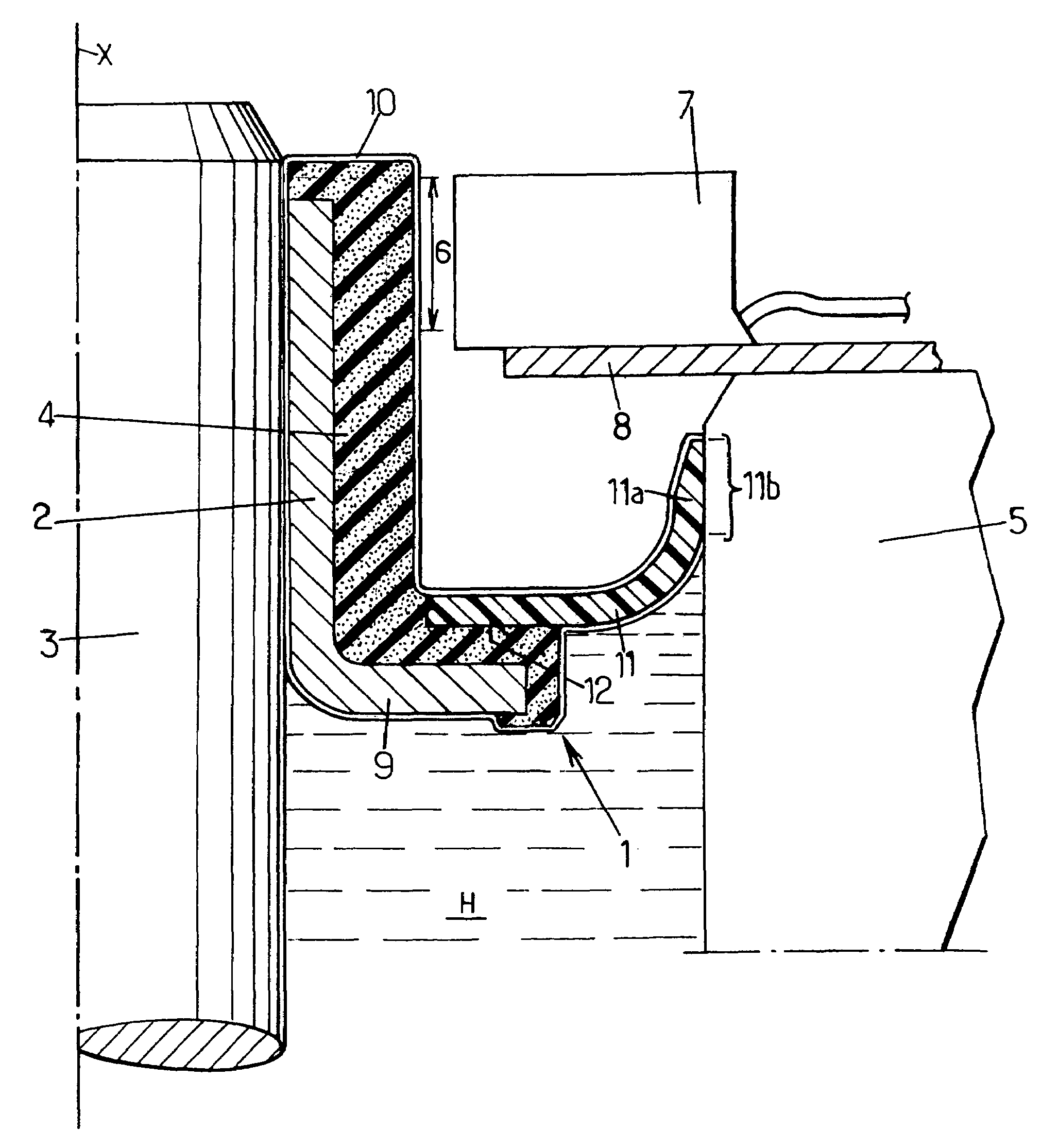
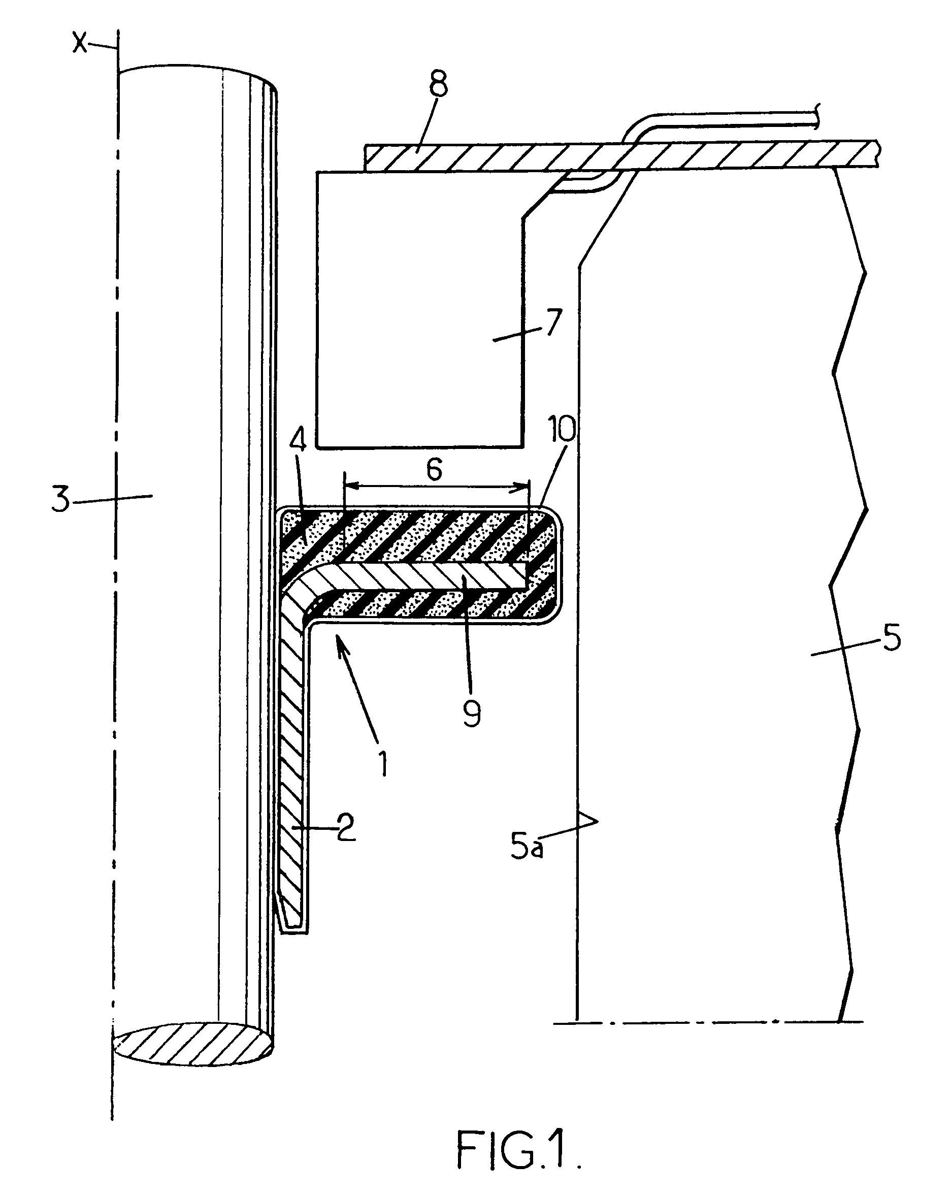
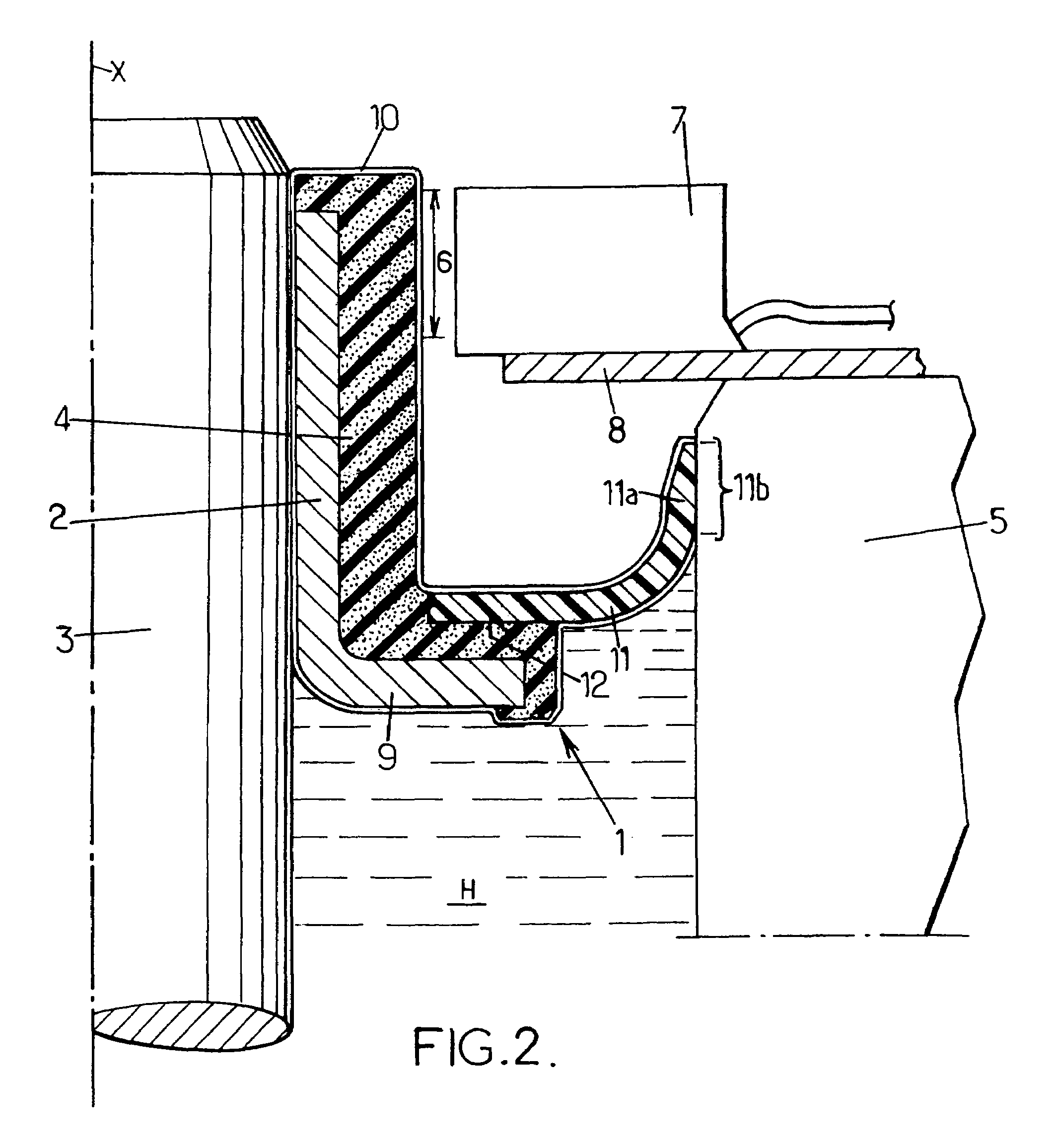
[0027]As can be seen in FIG. 1, the angle encoder comprises a sleeve 2 held in rotation on a rotary shaft 3, and an encoder element 4 of magnetizable polymer. Polarization marks are provided in a zone 6 referred to as the encoding zone of the encoder element.

[0028]A stationary casing 5 surrounding the angle encoder 1 serves as a stationary base for a sensor 7 secured to the casing via a plate 8.

[0029]The rotary shaft 3 may be constituted by any rotary machine shaft, for example a transmission shaft or a wheel shaft. It should be observed that the angle encoder 1 is not necessarily placed on a portion of the shaft that is surrounded by a stationary casing, but could be placed at a distance from any casing or bearing, providing a sensor can be held close to the encoding zone 6. Furthermore, the shaft may be a shaft that performs movement in translation, in which case the encoder serves to determine a linear position and / or speed.

[0030]The sleeve 2 is made of metal and is mounted on th...


PUM


Abstract

An encoder comprising a sleeve for holding on a shaft and an encoder element secured to the sleeve. The encoder element presents an encoding zone that is protected by a thin layer of material deposited by plasma directly on the encoder element and secured thereto, the thin layer covering at least the encoding zone A device including the encoder and a method of fabricating the encoder are described.

Description

[0001]The present invention relates to a displacement encoder for a movable shaft, and more particularly to an encoder comprising a sleeve for being held on the shaft, and an encoder element, in particular an element that is secured to the sleeve, the encoder element presenting an encoding zone provided with at least one polarization mark and protected by protection means.BACKGROUND OF THE INVENTION[0002]In numerous applications, and in particular for wheel shafts, outlet shafts from gearboxes, or crank shafts of internal combustion engines, a rotary shaft is fitted with a device for encoding angular displacement in order to measure its instantaneous speed of rotation and / or its angular position and / or its direction of rotation.[0003]It is advantageous to make the encoder element using a magnetizable polymer, i.e. a polymer of the elastomer type, or of any other material capable of performing a binder function, and containing a high proportion of magnetic particles, such as ferrite ...

Claims


Application Information

Patent Timeline
Patent Type & Authority Patents(United States)
IPC IPC(8): G01P3/48G01P3/487F16C19/08
CPCG01D5/12G01P3/487G01P3/443
Inventor GUERBE, LAURENTZARIFE, VICTOR
Owner HUTCHINSON SA
Why Eureka
Try Eureka