
Local network, particularly Ethernet network having redundancy properties, and coupling device for such a network

a technology of local network and redundancy property, which is applied in the field of local network, can solve the problems of error triggering, message received by the redundancy manager, risk of message copying or circulating within the network, etc., and achieve the effect of reducing the failure probability of the network, and further reducing the failure probability

Inactive Publication Date: 2008-06-10
SIEMENS AG
View PDF18 Cites 14 Cited by
  • Summary
  • Abstract
  • Description
  • Claims
  • Application Information

AI Technical Summary

Benefits of technology

This solution ensures quick detection and correction of errors, maintaining network availability by preventing accidental closure of connections and reducing failure probability without adding burdening test messages, thus ensuring continuous communication and payload data transmission.

Problems solved by technology

This means that messages received by the redundancy manager at its one port located in the ring are not forwarded via its other port located in the ring, but are blocked.
Networks in which messages are distributed from node to node and in which the response to the failure of a communication link between two nodes is to add a redundant communication path, have the risk that messages are copied or circulate within the network.
Such errors can be triggered when a redundant communication path is mistakenly added.
In the worst case, the maximum bandwidth of the network available for the data traffic is occupied, such that further payload traffic among the users connected to the network can no longer be transmitted.
When such an error occurs, the network is not available, or at least not fully available, for the connected users.

Method used


Image

  • Local network, particularly Ethernet network having redundancy properties, and coupling device for such a network
  • Local network, particularly Ethernet network having redundancy properties, and coupling device for such a network

Examples


Embodiment Construction

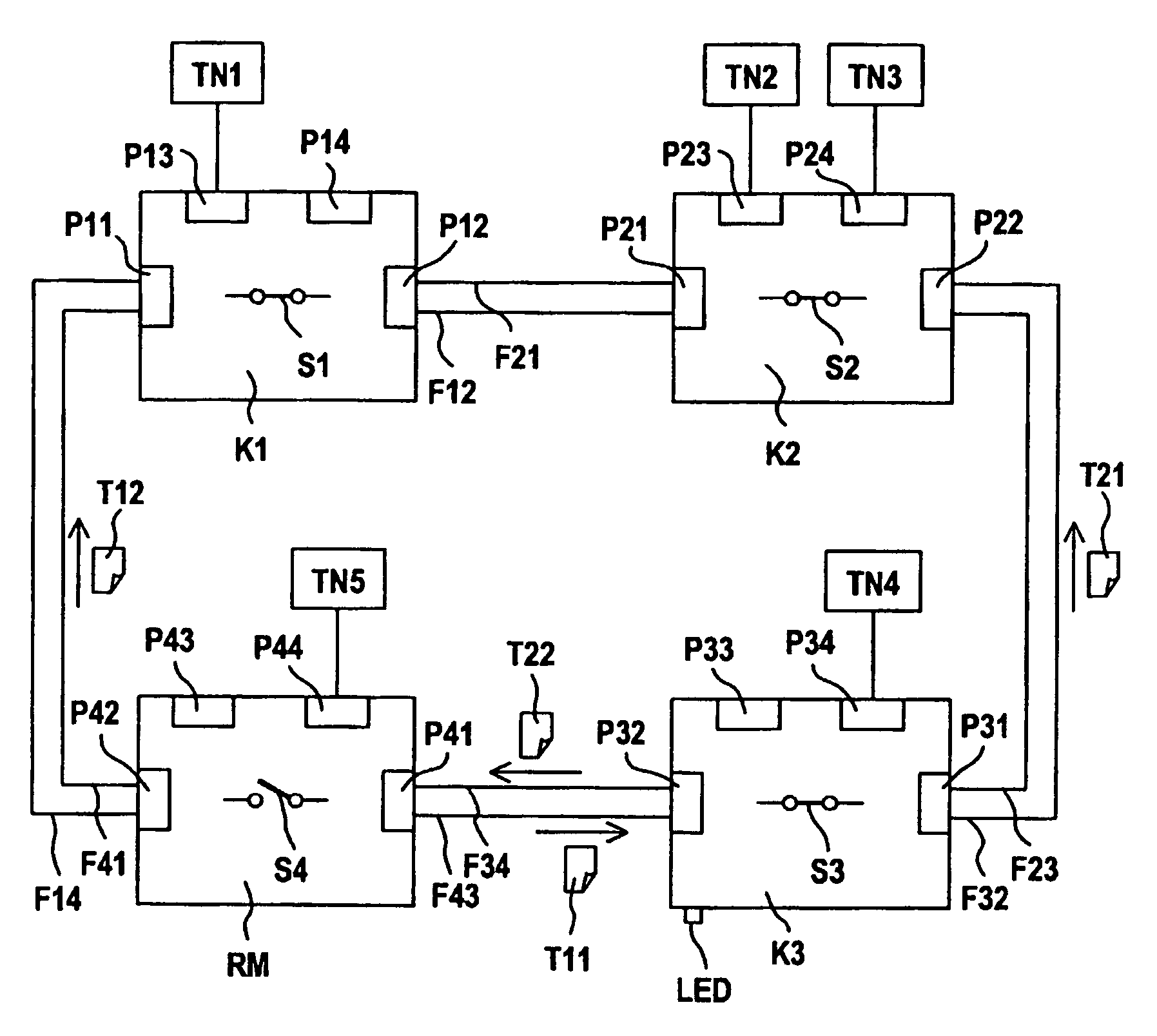
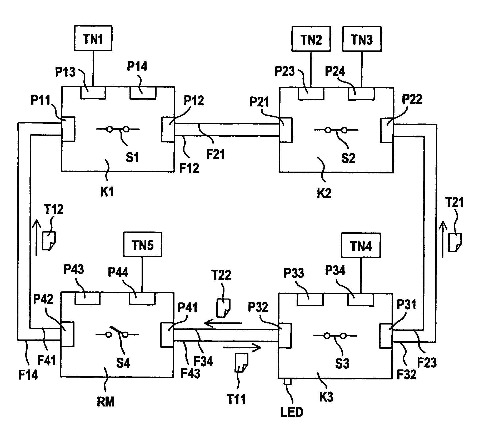
[0019]In a network, four coupling devices K1, K2, K3 and RM are interconnected, and the coupling device RM is operated as a redundancy manager. The coupling devices each have four ports, P11-P14, P21-P24, P31-P34 and P41-P44, respectively, to which connecting lines for the reception and transmission of messages can be connected. The coupling devices K1 to K3 and RM are configured as layer 2 components, i.e., they route messages in accordance with an internally stored address table. They are interconnected into a ring-shaped topology such that two ports of adjacent devices are connected. For this purpose, the ports P12 and P21 are interconnected by fibers F12 and F21 of a glass fiber cable. Copper cable can of course be used as an alternative. The fiber F12 serves to transmit messages from port P12 of the coupling device K1 to the port P21 of the coupling device K2. In the opposite direction, messages are transmitted from the port P21 of the coupling device K2 to the port P12 of the ...


PUM


Abstract

A local network, particularly an Ethernet network having redundancy properties, in which coupling devices (K1, K2, K3) and a redundancy manager (RM) are interconnected in a ring-shaped topology. The redundancy manager opens the ring to create a linear topology if test messages (T11, T12) emitted by the redundancy manager (RM) are received at the other port (P42, P41) within a given period of time, otherwise the redundancy manager (RM) closes the connection. As a so-called redundancy manager observer, at least one of the coupling devices (K3) is configured such that it evaluates messages received at the port (P32) thereof, the port (P32) being connected to the redundancy manager, opens the ring to create a linear topology, and signals an error if more than initial test messages (T11) have been received at this port (P32) and if the status “ring opened” has been indicated by the redundancy manager (RM) in the last-received initial test message (T11), whereby messages are prevented from circulating on the ring.

Description

CROSS-REFERENCE TO RELATED APPLICATIONS[0001]This is a Continuation of International Applications PCT / DE03 / 00553 and PCT / DE03 / 00555 both with an international filing date of Feb. 21, 2003, which were both published under PCT Article 21(2) in German, and the disclosures of which are incorporated into this application by reference.FIELD OF AND BACKGROUND OF THE INVENTION[0002]The present invention is related to a local network, particularly an Ethernet network, having redundancy properties and a coupling device for such a network.[0003]A local Ethernet network with redundancy properties is known from WO 99 / 46908. In the network described therein, coupling devices and a redundancy manager, each having at least two ports and being configured as layer 2 components, are interconnected in a ring-shaped topology by connecting two ports of adjacent devices. The term “layer 2 components” means that at least the layers 1 and 2 of the ISO OSI 7-layer model are implemented in the devices. The de...

Claims


Application Information

Patent Timeline
Patent Type & Authority Patents(United States)
IPC IPC(8): H04J1/16G01R31/08H04L1/22H04L12/42H04L12/423H04L12/437H04L12/46H04L69/40
CPCH04L1/22H04L12/2697H04L12/42H04L12/423H04L12/437H04L12/4637H04L43/50H04L69/40
Inventor KOESTNER, MICHAELTHRUM, HARALD
Owner SIEMENS AG
Learn More