Series of shafts and manufactoring method

a technology of shafts and manufacturing methods, applied in the direction of remote-control toys, couplings, manufacturing tools, etc., can solve the problems of inability to manufacture press fittings, complex and expensive manufacturing of press fittings, and low manufacturing cost of devices, so as to achieve low manufacturing cost, low manufacturing cost, and low manufacturing cost

Active Publication Date: 2008-06-17
SEW-EURODRIVE GMBH & CO KG
View PDF8 Cites 38 Cited by
  • Summary
  • Abstract
  • Description
  • Claims
  • Application Information

AI Technical Summary

Benefits of technology

[0008]An example embodiment of the present invention may provide a shaft fixture, in which the manufacturing and storage costs may be kept low and the shaft fixture may therefore be able to be manufactured inexpensively, with little outlay.

Problems solved by technology

However, such a device may be expensive to manufacture, since the transverse, threaded pin represents an additional part and a corresponding tap hole suitable for this transverse, threaded pin must be prepared.
Therefore, the manufacturing of the press-fit structure is complicated and expensive due to, in particular, the at least two fitting regions and the annular grooves.
Furthermore, it may be disadvantageous that a press fit for absorbing the axial forces is not present.
The manufacturing of this pinion fixture is also complicated and expensive, in particular, because of the annular grooves and the different outer diameters of the toothing and the fitting region.
In this instance, it may also be disadvantageous that no reassembly of an already previously assembled pinion fixture is possible, for it is clearly mentioned in column 3, line 12 of German Published Patent Application No. 41 34 552, that a press fit is provided.
The torque is transmitted by toothed, knurled or milled region B. It may be disadvantageous that region C cannot transmit a torque.
In this context, relative movements in regions A and C result in frictional fatigue fractures.
It may also be disadvantageous that two fitting regions (regions A and C) are necessary, and that a large overall length is consequently necessary.
In addition, the manufacture of two fitting regions is very expensive.
Furthermore, the bore has three different diameters, which are also difficult to fabricate.
Such a shaft fixture is also expensive to manufacture.
This variant is also expensive, since the fitting regions and the inner walls of the bore must be machined so accurately, that, on one hand, no shavings are formed when introducing the shaft for pressing it into the bore, and that, on the other hand, after insertion, i.e., in the pressed-in state after assembly, no gaps are formed between the shaft and the inner wall of the bore.
The torque is transmitted by toothed or milled region B. It may also be disadvantageous that region A cannot transmit a torque.
Reassembly is not possible or very difficult to carry out, since region C is longer than region B′ of the receiving part.
In this context, it may be disadvantageous that reassembly is only possible with great difficulty, for after shaft 1 is pressed into the receiving part and then extracted again, it is impossible to find the gear-tooth position upon reattaching the shaft for the purpose of reconnection, since in the case of a slightly attached shaft, the milled edge in region B1 is outside of the receiving part and cylindrical region B2 must be pressed in by force.
However, if cylindrical region B2 is reinserted deeply or far into the receiving part, it is only possible to rotate shaft 1 using a large force.
Thus, when the milled edge of region B1 lightly meets the knurled inner edge of the receiving part produced by the original joining procedure and then rotation occurs, it is extremely difficult to sense the engagement of the milled edge with the knurled inner edge, for the torques required for the rotation necessary for this are large and the torque fluctuations produced by the engagement of the milled edge are very small.
Thus, reassembly in a conventional manner, in particular, finding the engagement by hand, is impossible.

Method used


Image

  • Series of shafts and manufactoring method
  • Series of shafts and manufactoring method
  • Series of shafts and manufactoring method

Examples


Embodiment Construction

[0058]Example embodiments of the present invention are explained in detail with reference to the appended Figures.

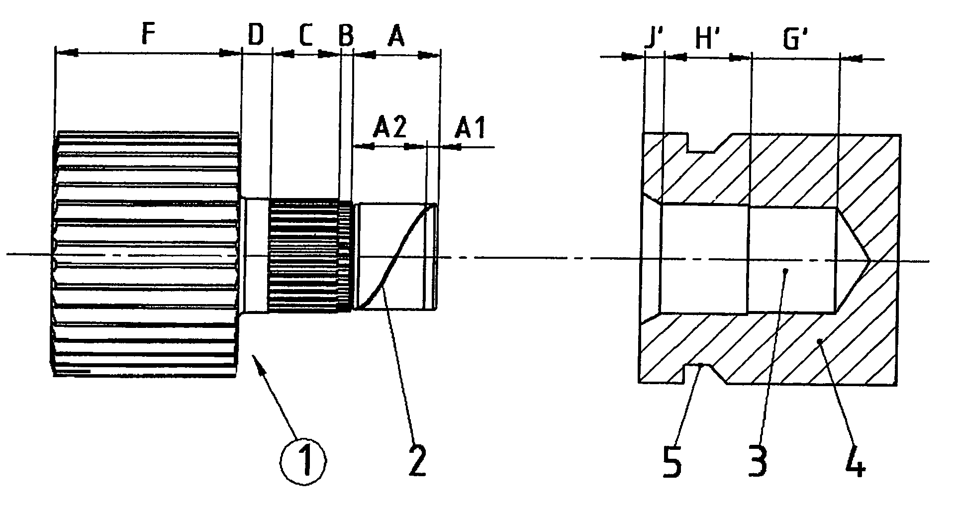
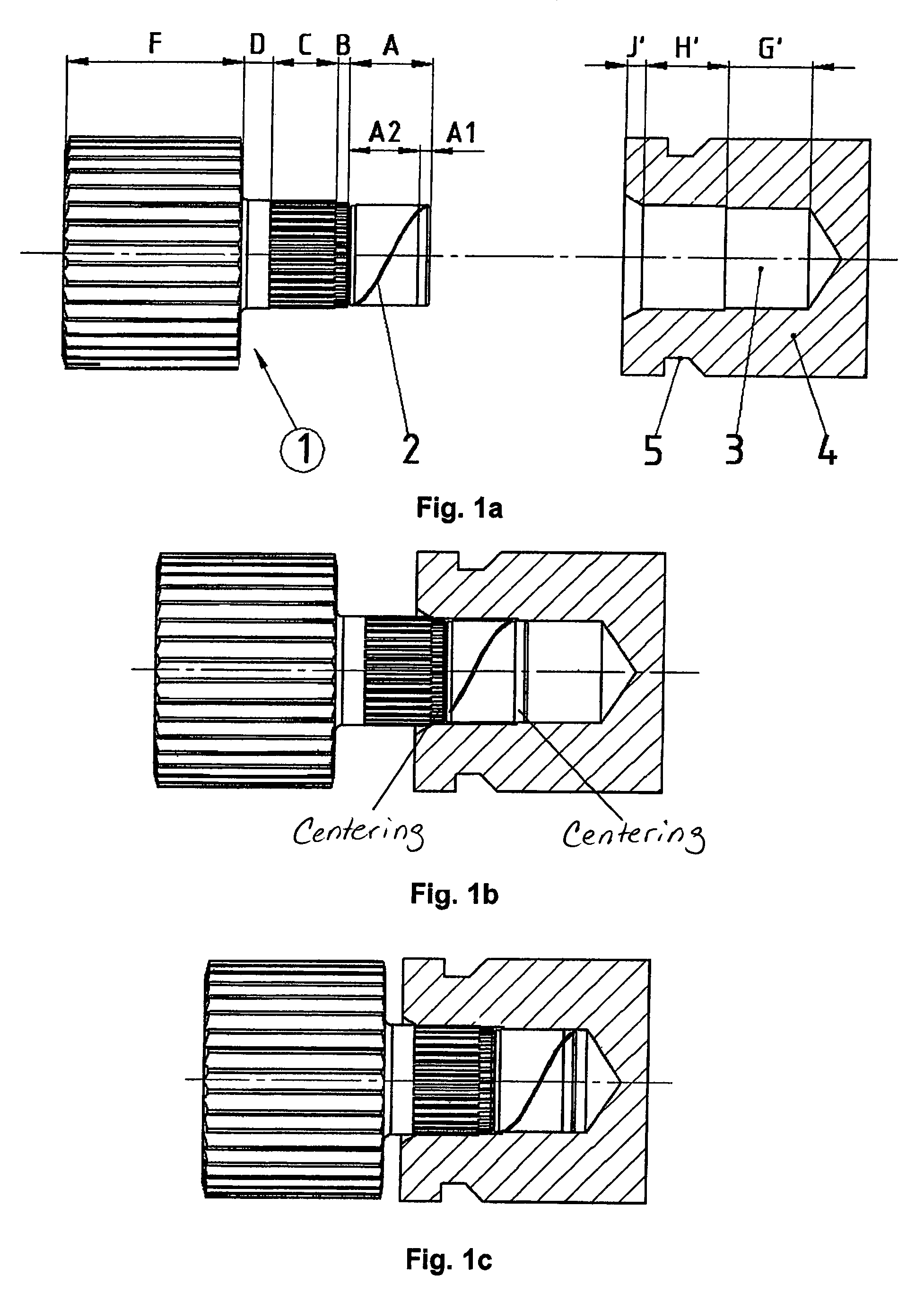
[0059]A shaft 1 and a receiving part 4 provided with a bore 3 are each separately illustrated in FIG. 1a.

[0060]In FIG. 1b, shaft 1 and receiving part 4 are illustrated at the start of assembly, i.e., when the shaft is lined up in receiving part 4.

[0061]In FIG. 1c, shaft 1 and receiving part 4 are illustrated at the end of assembly, i.e., in the pressed-in, fixed state.

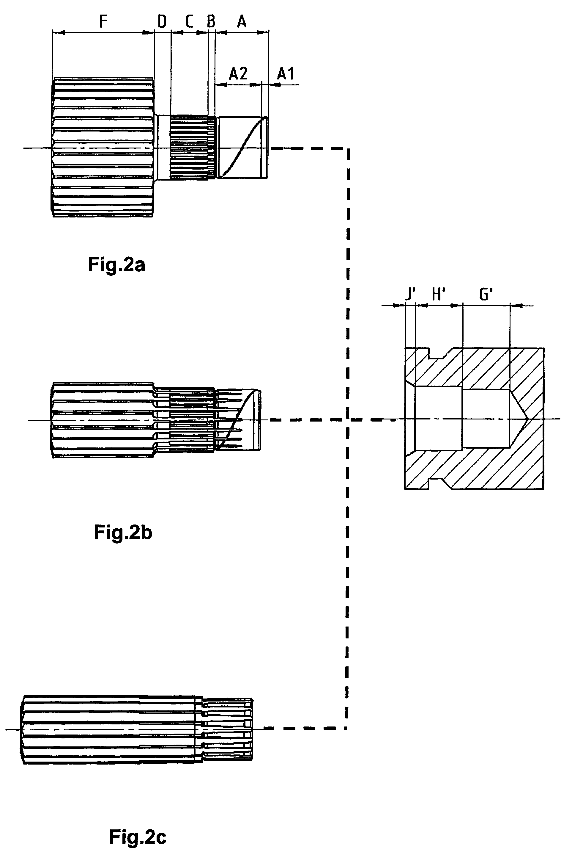
[0062]The attachment of different shafts of the series to a receiving part, for example, a coupling, is illustrated in FIGS. 2a, 2b and 2c. In this context, the different shafts are each individually denoted as FIG. 2a, FIG. 2b, and FIG. 2c.

[0063]Illustrated in FIG. 3a, FIG. 3b, and FIG. 3c is the attachment of a shaft constructed with different necks, to correspondingly different receiving parts, e.g., as a direct attachment to different motor shafts of a motor series.

[0064]An exemplary embodiment of the...


PUM

PropertyMeasurementUnit
temperatureaaaaaaaaaa
inner diameteraaaaaaaaaa

Abstract

A series of shafts configured to attach in a bore of a receiving part and a method for manufacturing the shafts, the series including at least two different sizes, each size including different variants of shafts; wherein each shaft includes at least five contiguous axial regions, wherein each variant includes different gear teeth in the axial region of the first end of the shaft. The bore in the receiving part includes at least three axially adjacent regions, the axial regions being arranged to provide a force-locked connection between the shaft and the receiving part when the shaft is pressed into the receiving part and such that the toothed or milled region of the shaft cuts into the bore in a form-locked manner as a result of the shaft being pressed in.

Description

FIELD OF THE INVENTION[0001]The present invention relates to a series of shafts and a manufacturing method. The present invention also relates to manufactured shanks.BACKGROUND OF THE INVENTION[0002]European Published Patent Application No. 0 339 380 describes a device for coaxially connecting two parts in a rotatably fixed manner, where a transverse, threaded pin is used for axial fixing. However, such a device may be expensive to manufacture, since the transverse, threaded pin represents an additional part and a corresponding tap hole suitable for this transverse, threaded pin must be prepared.[0003]A press-fit assembly for a rotor shaft is described in German Published Patent Application No. 37 32 223. In this context, the toothed region of a shaft is inserted into a bore of a receiving part, shavings being formed in response to the shaft being pressed in in a form-locked manner. Annular grooves are provided for collecting the shavings formed in response to the form-locked pressi...

Claims


Application Information

Patent Timeline
Patent Type & Authority Patents(United States)
IPC IPC(8): F16C3/00F16D1/072F16H57/00
CPCF16D1/072F16H57/0025F16D2001/103Y10T403/7035Y10T29/49865Y10T29/49945Y10T403/7028Y10T403/4966Y10T403/7026
Inventor HACKER, UWE
Owner SEW-EURODRIVE GMBH & CO KG
Why Eureka
Try Eureka