
Grinding apparatus

a grinding machine and grinding technology, applied in the direction of grinding machines, cleaning processes and equipment, dirt cleaning, etc., can solve the problems of large transportation costs, difficult to stand on the ground and guide the grinding machine manually, and large costs for setting workshops. , to achieve the effect of convenient handling

Inactive Publication Date: 2008-06-17
FLEX TRIM
View PDF22 Cites 9 Cited by
  • Summary
  • Abstract
  • Description
  • Claims
  • Application Information

AI Technical Summary

Benefits of technology

"The present invention is a grinding apparatus that is easy to handle and can be attached to vertical and horizontal surfaces. It includes a screen unit with a pipe connection that can be adjusted and replaced, and sealing members that create a tight seal with the surface. The grinding apparatus has a vacuum that holds it against the surface during operation, and it can be moved easily across the surface with minimal force. The grinding units can be enclosed by the screen unit, and the screen unit can be connected to satellite screen units for more efficient grinding. The grinding apparatus can also include wheels for easier movement on uneven surfaces. Overall, the grinding apparatus is designed to be self-attaching and self-propelling, and it can be controlled from a remote control."

Problems solved by technology

It will be a great disadvantage if one is obliged to grind everything indoors, since it will imply large costs for establishing workshops that are large enough for e.g. tower elements, ships and the like to be indoor during the grinding process.
Furthermore, it may entail large transportation costs in cases where the element to be ground is to be transported to a grinding workshop.
Another problem with grinding large elements or grinding high-level surfaces is that it may be difficult to stand on the ground and guide the grinding apparatus manually.
The disadvantage of a longitudinally adjustable handle in connection with a commonly known grinding apparatus for grinding approximately vertical surfaces is that it is difficult to apply correct pressure on the grinding disc for ensuring efficient grinding, and that the handle is to have a certain dimension for withstanding the weight of the grinding apparatus.
This implies a cumbersome handling of the grinding apparatus and risk of bad surface grinding.
The disadvantage of this grinding apparatus is that:the grinding apparatus under use is to be pressed down against a surface, and the applied pressure is to be maintained manually for continuous grinding of the surface.
This results in that the spacer member looses its sealing function, unless the operator is applied further pressure, which may be a drawback as the effect of the grinding is increased thereby.

Method used


Image

  • Grinding apparatus
  • Grinding apparatus
  • Grinding apparatus

Examples


second embodiment

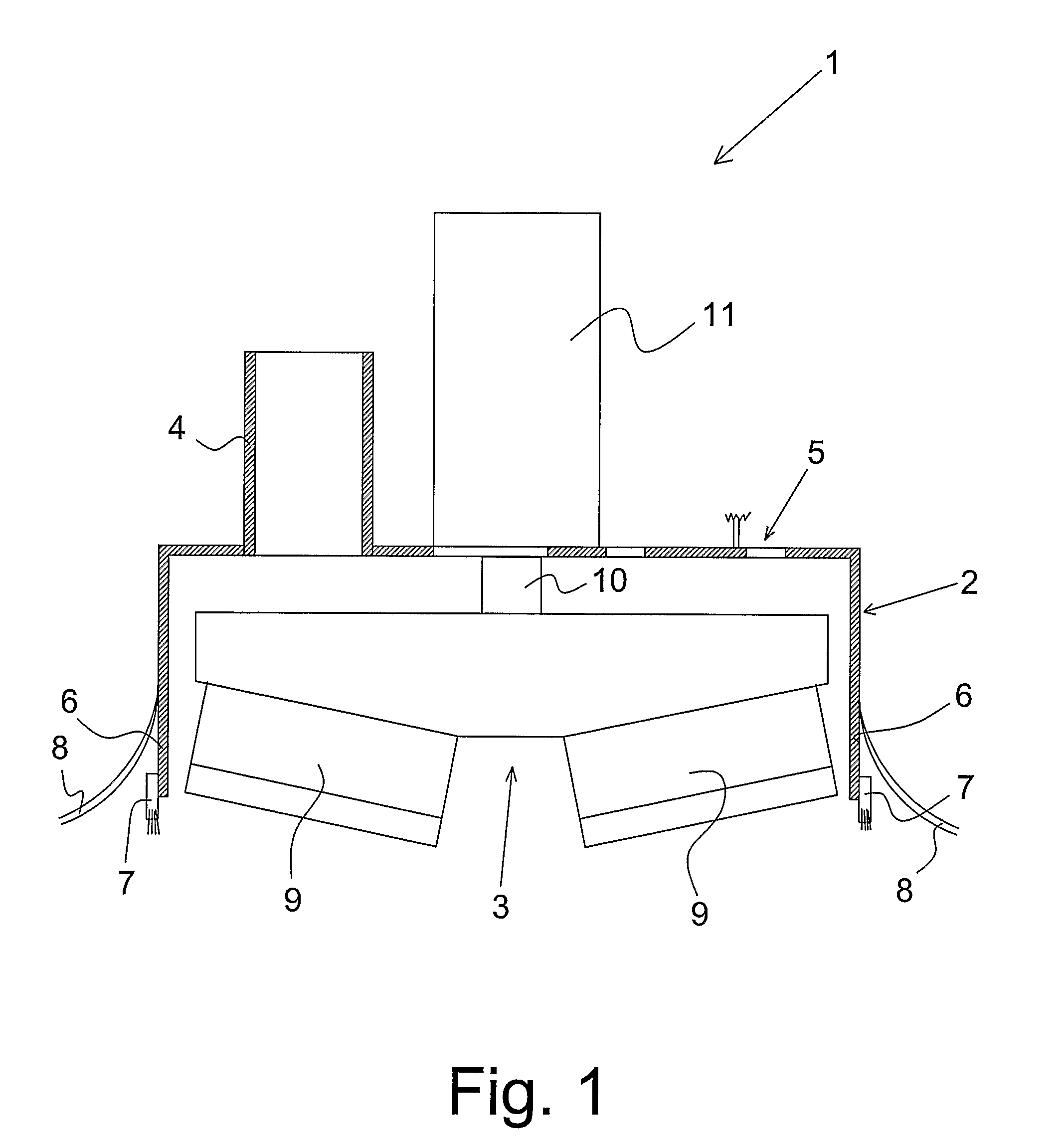
[0030]In the present invention, the screen unit with the pipe connection is connected to satellite screen units that each enclose a number of the grinding units.

[0031]This means that a central screen unit is provided, for example, to which the suction unit is connected and a number of satellite screen unit enclosing a number of grinding units, and where it is the central screen unit that provides for the grinding apparatus being held firmly against the surface while the surface grinding occurs in the connected satellite screen units.

[0032]In order to ensure that abraded material is removed from the screen unit with grinding units, these are preferably connected with the suction unit, however, without creating so much vacuum in the screen units that they are hold fast to the surface.

[0033]The adjustable spacer members and the sealing members enable moving the grinding apparatus without any problems across the surface, entailing that no great force is to be applied for moving the grin...

fourth embodiment

[0051]In the present invention, the suction units may be fans which by means of a ventilator forms a subpressure / vacuum in the screen units, whereby the grinding apparatus is held onto the surface and the abraded material is removed.

[0052]In order to avoid whirling abraded material out into the air by using the grinding apparatus, presenting a hazard for persons standing in the vicinity, the grinding apparatus is designed with a number of screen units with at least one pipe connection for connecting one or more suction units that may form a vacuum in the screen unit and suck the abraded material via the pipe connection out from the screen unit and on to e.g. a collecting container.

[0053]In order to grind large areas, the grinding apparatus is designed so that a plurality of grinding units are mounted in the same screen unit. For example, there may be four juxtaposed circular grinding wheels in a grinding unit, whereby a rapid surface grinding of a large surface may be attained. Thes...


PUM


Abstract

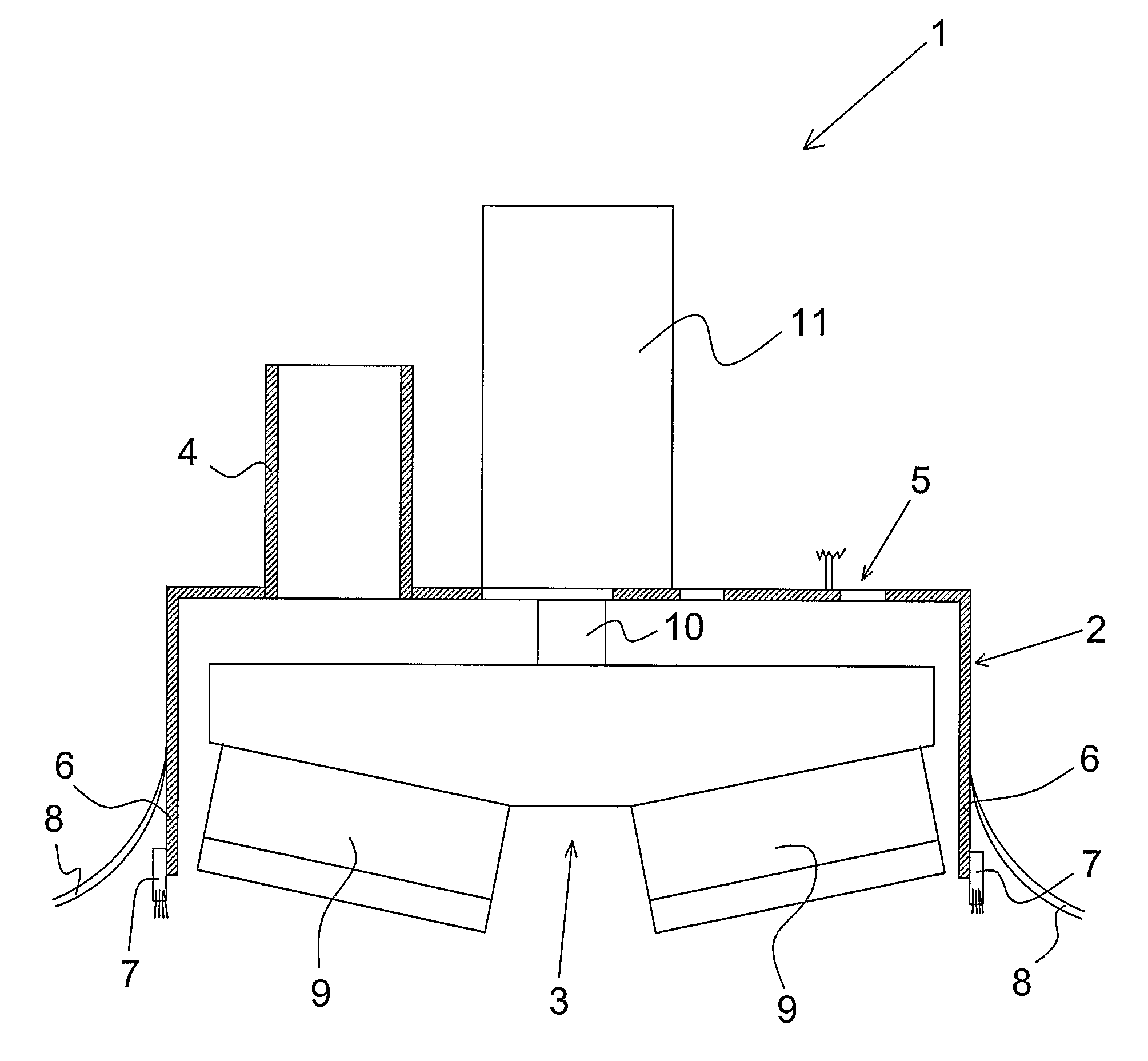
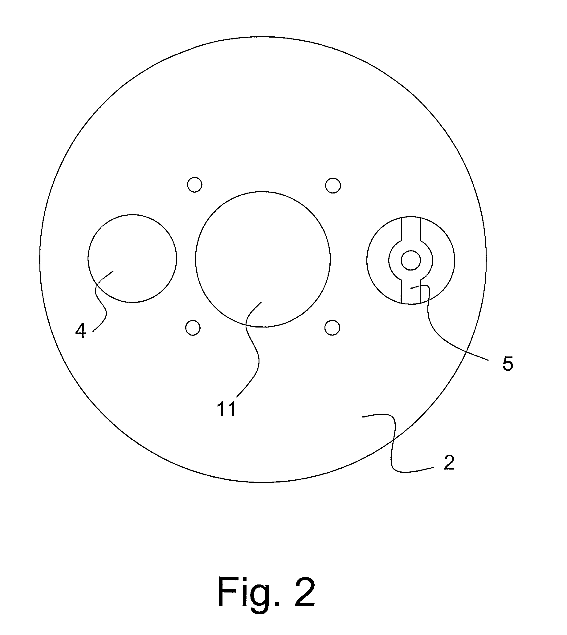
The present invention concerns a grinding apparatus (1) including a number of grinding units (3), a number of drive units (11) and a number of screen units (2), where a number of the grinding units (3) are enclosed by at least one of the screen units (2), and where at least one the screen units (2) is arranged with a pipe connection (4) adapted for connecting one or more suction units (21), where the screen unit (2) with the pipe connection (4) is designed along a lower edge (6) with a number of spacer members (7) that are arranged adjustable and replaceable, and a number of sealing members (8) that fit tightly to an underlying surface, that the spacer members (7) establish an adjustment of spacing of the grinding units (3) relatively to an underlying surface, and that the sealing members (8) interact with the suction units (21) for forming a vacuum that holds the grinding apparatus (1) against the said surface during operation.

Description

[0001]This application claims the benefit of Danish Application No. PA 2003 01806 filed Dec. 8, 2003, Danish Application No. PA 2004 01457 filed Sep. 24, 2004 and PCT / DK2004 / 000848 filed Dec. 8, 2004, which are hereby incorporated by reference in their entirety.FIELD OF THE INVENTION[0002]The present invention concerns a grinding apparatus including a number of grinding units, a number of drive units and a number of screen units, where a number of the grinding units are enclosed by at least one of the screen units, and where at least one of the screen units is arranged with a pipe connection adapted for connecting one or more suction units.BACKGROUND OF THE INVENTION[0003]When grinding large surfaces, such as the hull of a ship, windmill wings or large tower elements, presently handheld grinding apparatuses are used which are moved back and forth on the surface to be ground.[0004]The person using the grinding apparatus is usually to walk with respiratory protection and safety goggle...

Claims


Application Information

Patent Timeline
Patent Type & Authority Patents(United States)
IPC IPC(8): B24B23/00A47L11/40B08B15/04B24B7/18B24B55/10
CPCB08B15/04B24B7/182B24B7/186B24B55/102
Inventor JESPERSEN, POUL ERIK
Owner FLEX TRIM
Learn More