
PVT variation detection and compensation circuit

a compensation circuit and variation detection technology, applied in the field of integrated circuits, can solve problems such as hammering the performance of the ics, erroneous circuit output, and change in slew ra

Active Publication Date: 2008-06-17
NXP USA INC
View PDF10 Cites 13 Cited by
  • Summary
  • Abstract
  • Description
  • Claims
  • Application Information

AI Technical Summary

Problems solved by technology

PVT variations are a critical factor that can hamper the performance of the ICs.
Therefore, a change in the setup or hold times corresponding to any one component can result in an erroneous circuit output.
PVT variations can also result in a change in slew rates, increase in current leakage, and electromagnetic interference (EMI).
Therefore, such techniques might not provide adequate compensation.
Finally, these techniques involve additional process steps, which are complex in nature.

Method used


Image

  • PVT variation detection and compensation circuit
  • PVT variation detection and compensation circuit
  • PVT variation detection and compensation circuit

Examples


Embodiment Construction

[0017]The detailed description in connection with the appended drawings is intended as a description of the presently preferred embodiments of the present invention, and is not intended to represent the only form in which the present invention may be practiced. It is to be understood that the same or equivalent functions may be accomplished by different embodiments that are intended to be encompassed within the spirit and scope of the present invention.

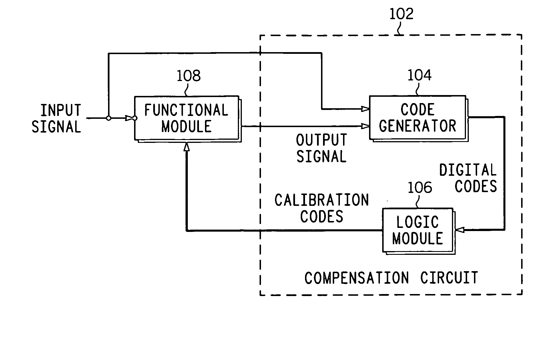
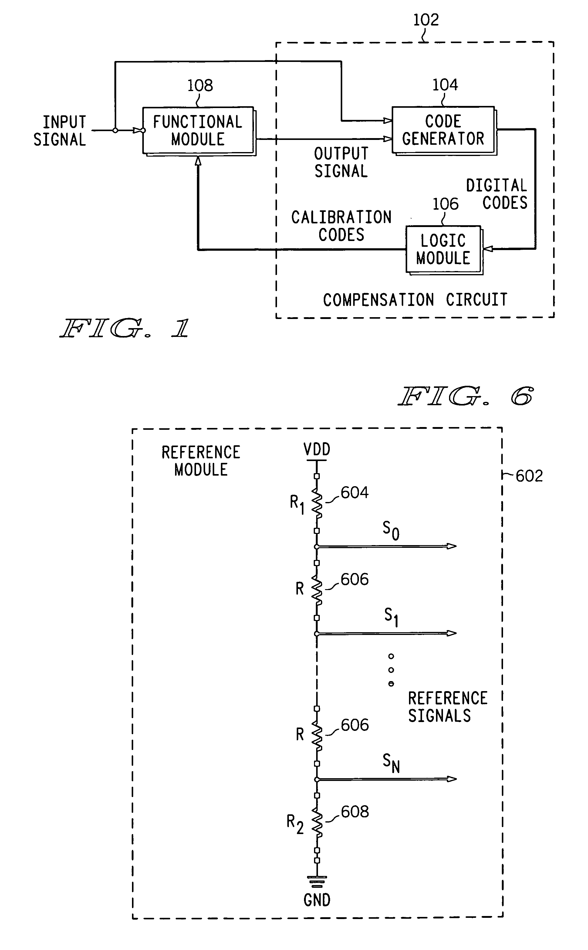
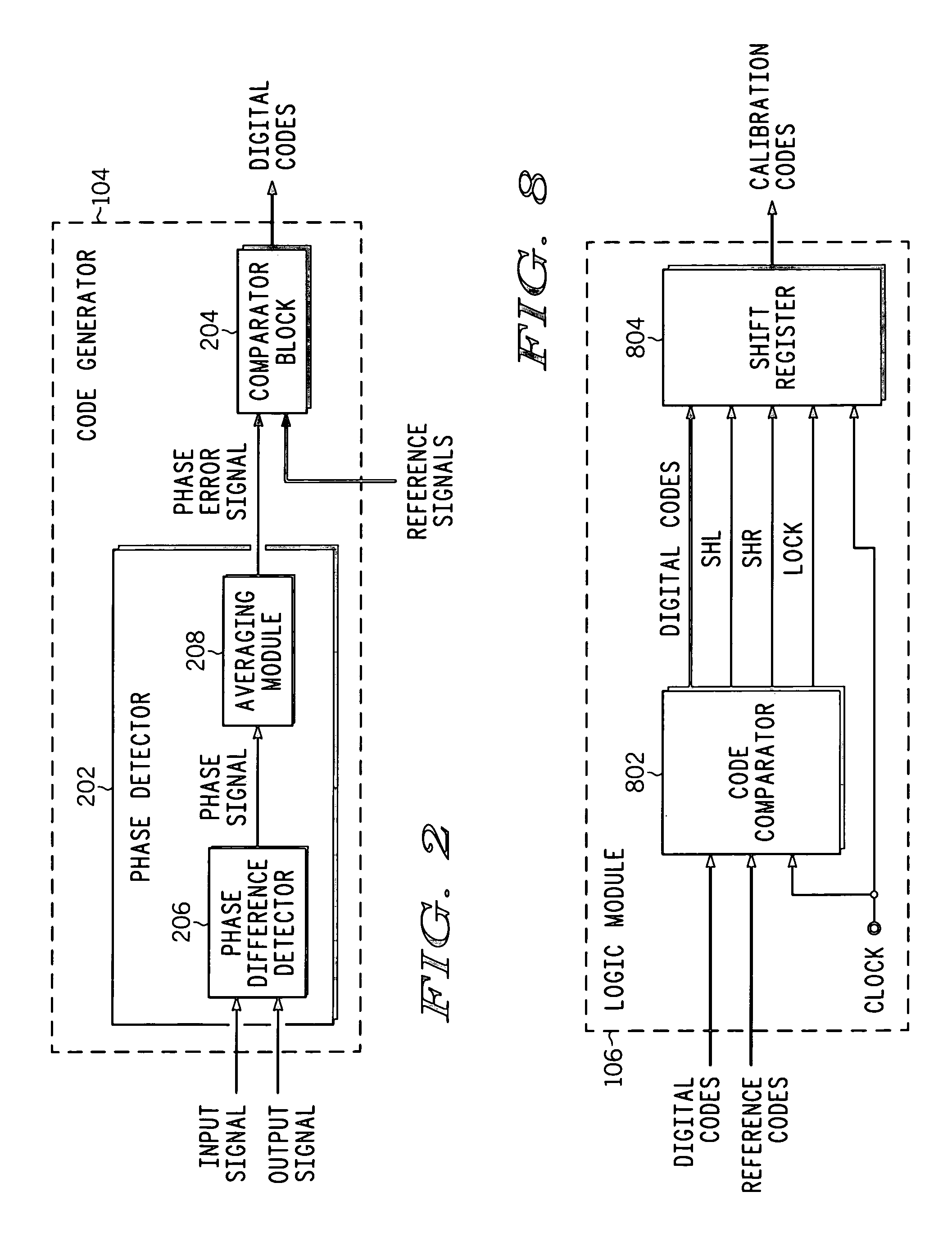
[0018]The present invention provides a compensation circuit for compensating for PVT variations in an integrated circuit. The integrated circuit includes a plurality of functional modules, each of which includes a set of functional units, and generates an output signal in response to an input signal. The compensation circuit includes a code generator and a logic module. The code generator generates a digital code for each functional unit from amongst the set of functional units. The digital codes are based on phase differences between...


PUM


Abstract

A compensation circuit and a method for compensating for process, voltage and temperature (PVT) variations in an integrated circuit (IC). The IC includes several functional modules, each of which includes a set of functional units, and generates an output signal in response to an input signal. The compensation circuit includes a code generator and a logic module. The code generator generates a digital code for each functional unit. The digital codes are based on phase differences between the input signal and the output signal. The logic module generates calibration codes based on the digital codes. The calibration codes compensate for the PVT variations in the corresponding functional units.

Description

BACKGROUND OF THE INVENTION[0001]The present invention relates generally to the field of integrated circuits (ICs) and, in particular, to process, voltage and temperature (PVT) variations in ICs.[0002]PVT variations are a critical factor that can hamper the performance of the ICs. For example, PVT variations can result in a change in setup and hold times of synchronous circuits. Different components of a synchronous circuit are driven by a common system clock. Therefore, a change in the setup or hold times corresponding to any one component can result in an erroneous circuit output. PVT variations can also result in a change in slew rates, increase in current leakage, and electromagnetic interference (EMI).[0003]One technique for reducing PVT variations in a circuit is based on sensing variations in the operation of the circuit and taking appropriate action to reduce these variations. For example, if a variation in the signal delay is identified, then the input signal delay is chang...

Claims


Application Information

Patent Timeline
Patent Type & Authority Patents(United States)
IPC IPC(8): H01L35/00H01L37/00H03K17/78H03K3/42
CPCH03K19/00369
Inventor GK, SIDDHARTHAKHAN, QADEER A.TRIPATHI, DIVYAWADHWA, SANJAY KMISRI, KULBHUSHAN
Owner NXP USA INC
Learn More