Solid electrolytic capacitor and method for producing the same

a solid electrolytic capacitor and electrolytic capacitor technology, applied in the manufacture of electrolytic capacitors, variable capacitors, fixed capacitors, etc., can solve the problems of increasing the leakage current, uneven thickness of electrically conducting polymers attached, and the inability to achieve desirable capacitance of solid electrolytic capacitors, etc., to achieve the improvement of one-dimensional properties of polymer chains, improve the effect of capacitor properties and increase the electrical conductivity

Active Publication Date: 2008-06-17
MURATA MFG CO LTD
View PDF18 Cites 46 Cited by
  • Summary
  • Abstract
  • Description
  • Claims
  • Application Information

AI Technical Summary

Benefits of technology

[0010]Therefore, with a view to solving the above-described problems, the objects of the present invention are, to fabricate a solid electrolytic multilayer capacitor having a high capacitance and a low equivalent series resistance by stably producing thin elements having a smaller variety in shape to increase the number of elements to be stacked inside the capacitor with the time involved for precisely controlling polymer formation being reduced without increasing in short-circuit failure rate, and to provide a production process therefor.
[0109]In the present invention, the compression may be performed after the electrically conducting layer is formed. This is particularly effective. For example, in the case of an electrically conducting layer containing an elastic body, plastic deformation occurs by the compression, to further reduce the thickness and an effect of smoothing the electrically conducting layer surface is also provided.

Problems solved by technology

However, in a solid electrolytic capacitor, if the polymerization conditions are not precisely controlled in the step of attaching an electrically conducting polymer to the cathode part, the thickness of the electrically conducting polymer attached becomes uneven, and the electrically conducting polymer is too thin in some portions, giving rise to problems such that the paste or the like readily comes into direct contact with the oxide dielectric film layer to cause increase in the leakage current.
Since the number of capacitor elements which can be stacked in a predetermined chip is restricted by the thickness of the element, desirable capacitance of solid electrolytic capacitor has not been achieved.
Moreover, if the thickness of the electrically conducting polymer attached is uneven, the contacting area between the stacked capacitor elements becomes small, giving rise to a problem that the equivalent series resistance (ESR) becomes large.
Precise control of polymerization conditions for a long time of period, which is required for obtaining an electrically conducting polymer with a smaller variety in thickness, raises a problem that such a requirement greatly deteriorates the productivity.

Method used


Image

  • Solid electrolytic capacitor and method for producing the same
  • Solid electrolytic capacitor and method for producing the same
  • Solid electrolytic capacitor and method for producing the same

Examples


example 1

[0115]A formed aluminum foil (thickness: 100 μm) was cut into a size of 3 mm (short axis direction)×10 mm (long axis direction) and a polyimide solution was circumferentially coated on both surfaces to a width of 1 mm to section the surface area into a 4-mm portion and a 5-mm portion in the long axis direction, and then dried to form a masking. The 3 mm×4 mm portion of this formed foil was electrochemically formed with an aqueous 10 mass % ammonium adipate solution by applying a voltage of 4 V to form an oxide dielectric film on the cut end part. Thereafter, this 3 mm×4 mm portion of the aluminum foil was dipped in 1.2 mol / L of an isopropyl alcohol (IPA) solution having dissolved therein 3,4-ethylenedioxythiophene for 5 seconds, dried at room temperature for 5 minutes, and then dipped for 5 seconds in 2 mol / L of an aqueous ammonium persulfate solution containing sodium 2-anthraquinonesulfonate adjusted to a concentration of 0.07 mass %. Subsequently, this aluminum foil was left stan...

examples 2 (

EXAMPLES 2(1) TO 2(3)

[0121]A solid electrolyte was formed under the same production conditions as in Example 1 and subjected to various combinations of compression and stacking.

EXAMPLE 2(1)

[0122]A capacitor element was fabricated in the same manner as in Example 1 except that each of the formed aluminum foil substrate having thereon a solid electrolyte was compressed in the thickness direction after carbon paste and silver paste were attached on the surface, four of thus obtained aluminum foils were stacked and a cathode lead terminal was connected thereto.

EXAMPLE 2(2)

[0123]A capacitor element was fabricated in the same manner as in Example 1 except that the substrate having provided thereon a solid electrolyte was compressed in the thickness direction, four of thus obtained capacitor elements were stacked, the stacked body was compressed in the thickness direction, carbon paste and silver paste were attached thereon and a cathode lead terminal was connected thereto.

example 2 (

EXAMPLE 2(3)

[0124]A capacitor element was fabricated in the same manner as in Example 1 except that four substrates each having provided thereon a solid electrolyte were stacked, the stacked body was compressed in the thickness direction, carbon paste and silver paste were attached thereon and a cathode lead terminal was connected thereto.

[0125]The obtained capacitors were evaluated on the properties in the same manner as in Example 1 and the results are shown in Table 1.


PUM

PropertyMeasurementUnit
heightaaaaaaaaaa
boiling pointaaaaaaaaaa
temperatureaaaaaaaaaa

Abstract

A solid electrolytic capacitor comprising a capacitor element obtainable by compressing a porous valve-acting metal substrate having on the dielectric film surface thereof a solid electrolyte layer containing an electrically conducting polymer in the thickness direction, wherein assuming that the maximum thickness and the minimum thickness of the electrically conducting polymer layer including the substrate before the compression are Hamax and Hamin, and the maximum thickness and the minimum thickness of the electrically conducting polymer layer after the compression are Hbmax and Hbmin, the percentage decrease ΔH in the difference of thickness represented by the following formula is preferably from 5 to 95%: Formula (I). The thin solid electrolytic capacitor element of the present invention, which can be stably produced with a small variety in shape, enables fabrication of a solid electrolytic multilayer capacitor having a high-capacitance and small-size with a low height, which, free from short-circuit failure, exhibits stable performanceΔ⁢⁢H⁡(%)=[1-(Hb⁢⁢max-Hb⁢⁢min)(Ha⁢⁢max-Ha⁢⁢min)]×100.(I)

Description

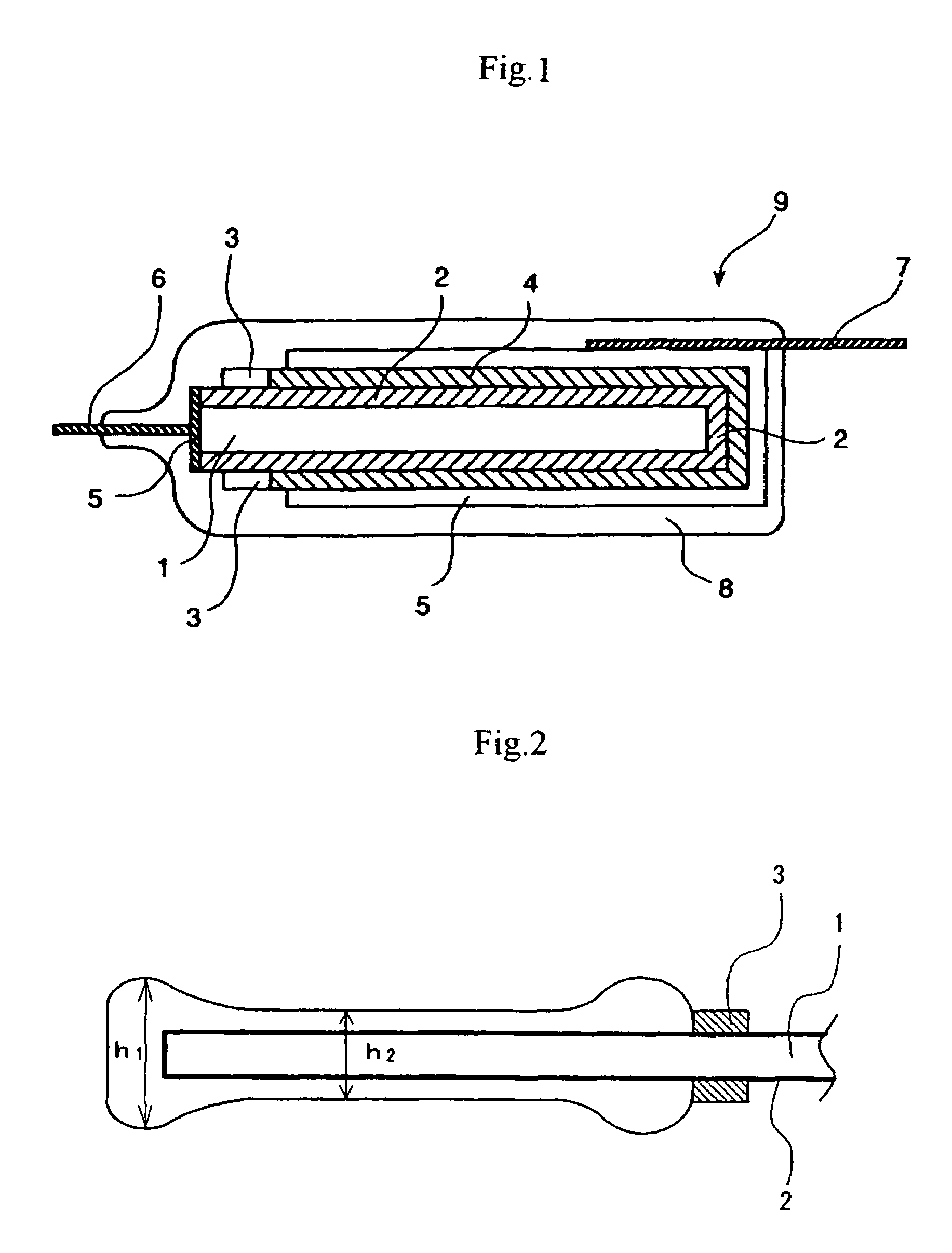
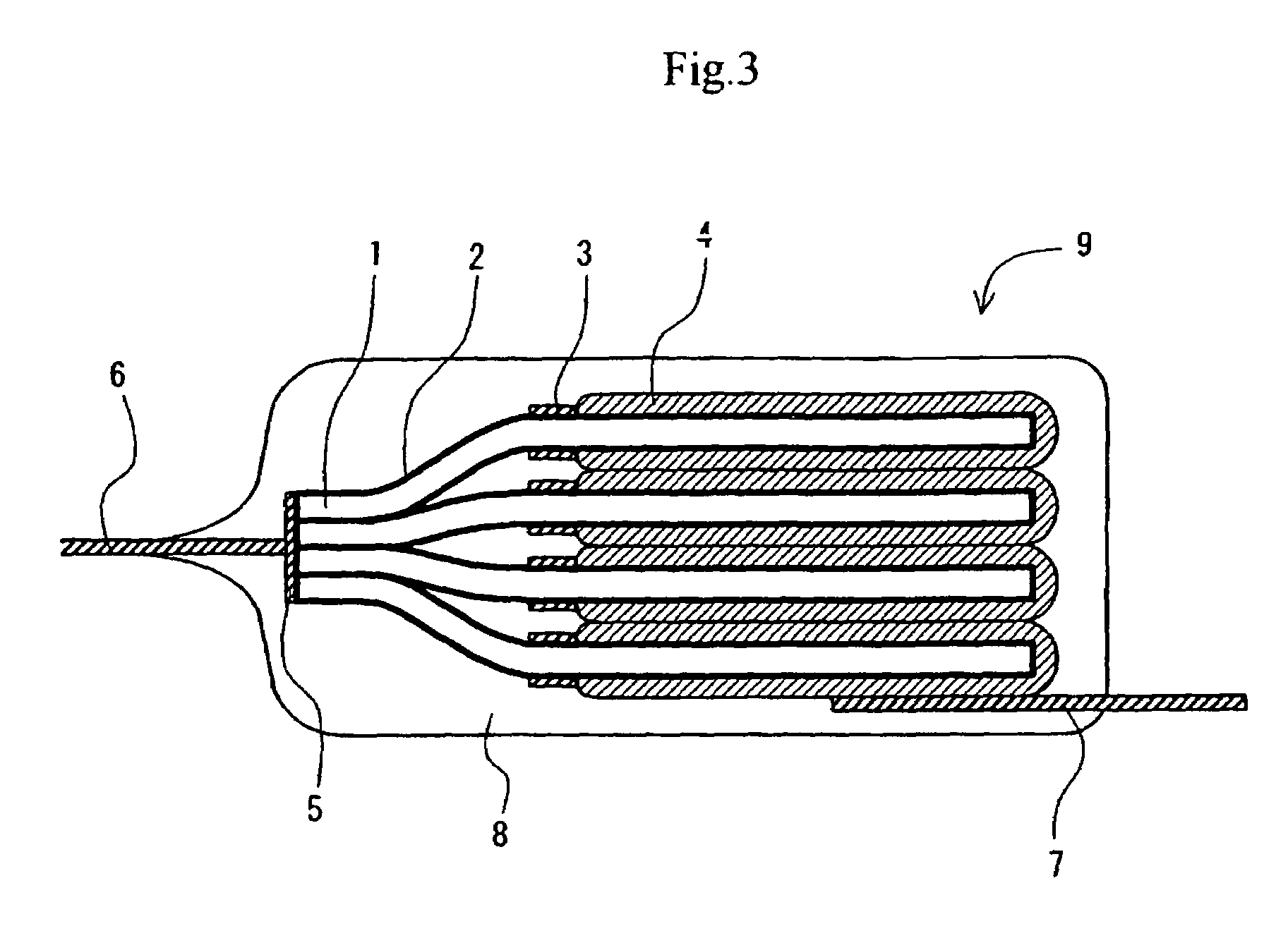
CROSS-REFERENCE TO RELATED APPLICATION[0001]This is an application based on the prescription of 35 U.S.C. Section 111(a) with claiming the benefit of filing date of U.S. Provisional application Ser. No. 60 / 430,063 filed Dec. 2, 2002 under the provision of 35 U.S.C. Section 111(b), pursuant to 35 U.S.C. Section 119(e)(1).TECHNICAL FIELD[0002]The present invention relates to a solid electrolytic capacitor using an electrically conducting polymer as a solid electrolyte layer, and a production method thereof.BACKGROUND ART[0003]A basic element of a solid electrolytic capacitor is generally produced, as shown in FIG. 1, by forming an oxide film layer 2 as a dielectric material on an anode substrate 1 comprising a metal foil having a specific surface area enlarged through etching treatment, forming a solid semiconductor layer (hereinafter referred to as a solid electrolyte) 4 as an opposing electrode in the outer side of the oxide film layer, and if desired, further forming an electricall...

Claims


Application Information

Patent Timeline
Patent Type & Authority Patents(United States)
IPC IPC(8): H01G9/04H01G9/00H01G9/145H01G9/15
CPCH01G9/0036H01G9/15Y10T29/417
Inventor KONUMA, HIROSHIKOBAYASHI, KENKISAWAGUCHI, TORU
Owner MURATA MFG CO LTD
Why Eureka
Try Eureka