Unlock instant, AI-driven research and patent intelligence for your innovation.

Determining data signal jitter via asynchronous sampling

a data signal and jitter technology, applied in the direction of noise figure or signal-to-noise ratio measurement, instruments, transmission monitoring, etc., can solve the problems of significant high-impedance data signal, compensation model may not be accurate, significant circuit area can be consumed in impedance-matched and isolated output pads

Inactive Publication Date: 2008-06-17
INT BUSINESS MASCH CORP
View PDF27 Cites 2 Cited by
  • Summary
  • Abstract
  • Description
  • Claims
  • Application Information

AI Technical Summary

Benefits of technology

The patent describes a method and apparatus for determining the jitter level of a data signal. The method involves analyzing raw data provided by an apparatus, which can be a test circuit or a production integrated circuit. The method collects values corresponding to edge positions of the data signal by sampling the output of an edge detector using a sampling clock signal that differs from the data rate. The sampled edge data is then analyzed to determine the relationship between the sampling clock and data rate, which is used to generate a timebase to fold the data. The values of the data signal are then analyzed in relation to the correct period to generate a histogram, which indicates the jitter of the data signal. The method can be embedded in a test instrument or a production integrated circuit. The invention provides a low-cost solution for determining data signal jitter level.

Problems solved by technology

In laboratory environments, high-accuracy laboratory instruments may be used to determine the jitter of a signal via very stable reference clocks and long integration times. However, the challenge of probing a very high frequency data signal and / or high-impedance data signal is significant, as the effects of the probe must be accounted for in the measurements and probe characteristics can vary over time and the probe compensation model may not be accurate under actual measurement conditions.
Further, significant circuit area can be consumed in the impedance-matched and isolated output pads that permit such precision measurements.
Such equipment is expensive and it is typically unfeasible to incorporate the equivalent of such instrumentation within production circuits.
Use of the internal global clock is limited in that clock jitter and data jitter cannot be separated.
When an external sample clock is used, the delay accuracy, and thus the accuracy of the jitter measurement, is difficult to control.
Since one inverter delay is typically the shortest delay available for fabricating an internal delay line, the resolution of the jitter measurement is then limited to one inverter delay.
When measuring the jitter level of low-jitter signals, the resolution of the delay line technique is insufficient for accurate results.
Further, if a large delay range is provided, the area and power required can be quite large, since the delay is typically operating at a very high clock frequency.

Method used


Image

  • Determining data signal jitter via asynchronous sampling
  • Determining data signal jitter via asynchronous sampling
  • Determining data signal jitter via asynchronous sampling

Examples


Embodiment Construction

[0027]The present invention concerns the measurement of jitter of data signals, and in particular, the measurement of jitter in interface data signals. In order to produce accurate results, the capture of measurement data is generally performed by a sampling circuit within the interface (or other data-receiving circuit) rather than a separate test probe. However, the techniques of the present invention can be applied to and within test equipment, as well.

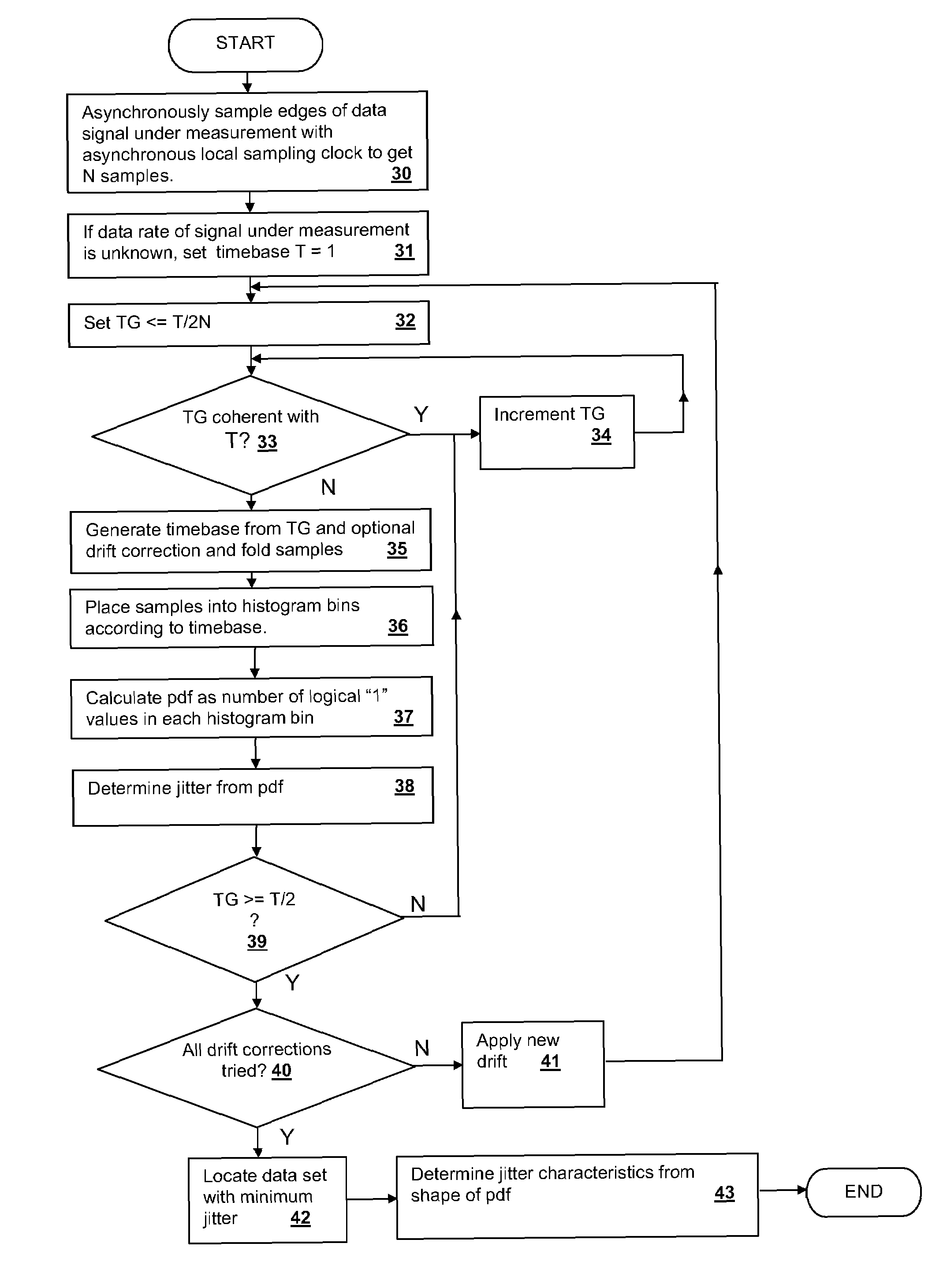
[0028]Primarily, the present invention provides new methods for analyzing data obtained by sampling a data signal under measurement with an asynchronous sampling clock. Rather than filtering the sampled data, as is done within a phase-lock loop (PLL) loop filter, the present invention resolves the sampled data to identify a relationship between the measured locations of data signal edges relative to the sampling clock and then determines the jitter of the measured data signal from the distribution of samples after folding the sample...


PUM


Abstract

A method for determining data signal jitter via asynchronous sampling provides a low cost and production-integrable mechanism for measuring data signal jitter. The data signal is edge-detected and sampled by a sampling clock of unrelated frequency the sampled values are collected in a histogram according to a folding of the samples around a timebase. The timebase is determined by sweeping to detect a minimum jitter for the folded data. The histogram for the correct estimated timebase period is representative of the probability density function of the location of data signal edges and the jitter characteristics are determined by the width and shape of the density function peaks. Frequency drift can be corrected by adjusting the timebase used to fold the data across the sample set.

Description

[0001]This invention was made with Government support under NBCH3039004, DARPA. THE GOVERNMENT HAS CERTAIN RIGHTS IN THIS INVENTION.CROSS-REFERENCE TO RELATED APPLICATIONS[0002]This application is related to U.S. applications: Ser. No. 11 / 279,651 entitled “METHOD AND APPARATUS FOR DETERMINING JITTER AND PULSE WIDTH FROM CLOCK SIGNAL COMPARISONS” filed on Apr. 13, 2006 and issued as U.S. Pat. No. 7,286,947 on Oct. 23, 2007, Ser. No. 11 / 427,831, entitled “METHOD OF GENERATING AN EYE DIAGRAM FOR INTEGRATED CIRCUIT TRANSMITTED SIGNALS”, and Ser. No. 11 / 427,860, entitled “METHOD AND APPARATUS FOR CONSTRUCTING A SYNCHRONOUS SIGNAL DIAGRAM FROM ASYNCHRONOUSLY SAMPLED DATA”, both filed concurrently with this application, by the same Inventors and assigned to the same Assignee. The specifications of the above-referenced applications are incorporated herein by reference.BACKGROUND OF THE INVENTION[0003]1. Technical Field[0004]The present invention relates generally to digital interface circui...

Claims


Application Information

Patent Timeline
Patent Type & Authority Patents(United States)
IPC IPC(8): G06F19/00
CPCG01R29/26G01R31/31709G01R31/31725H04L1/205
Inventor CRANFORD, JR., HAYDEN C.GEBARA, FADI H.SCHAUB, JEREMY D.
Owner INT BUSINESS MASCH CORP