Filter coefficient adjustment apparatus

a filter coefficient and coefficient technology, applied in the field of digital coherent optical receivers, can solve the problems of limited application, inability to implement convergence even, and relatively complex

a filter coefficient and coefficient technology, applied in the field of digital coherent optical receivers, can solve the problems of limited application, inability to implement convergence even, and relatively complex

US20100003028A1Active Publication Date: 2010-01-07FUJITSU LTD

Image

  • Filter coefficient adjustment apparatus
  • Filter coefficient adjustment apparatus
  • Filter coefficient adjustment apparatus

Examples


Embodiment Construction

[0053]The embodiments of the present invention will be described in detailed in conjunction with the attached drawings.

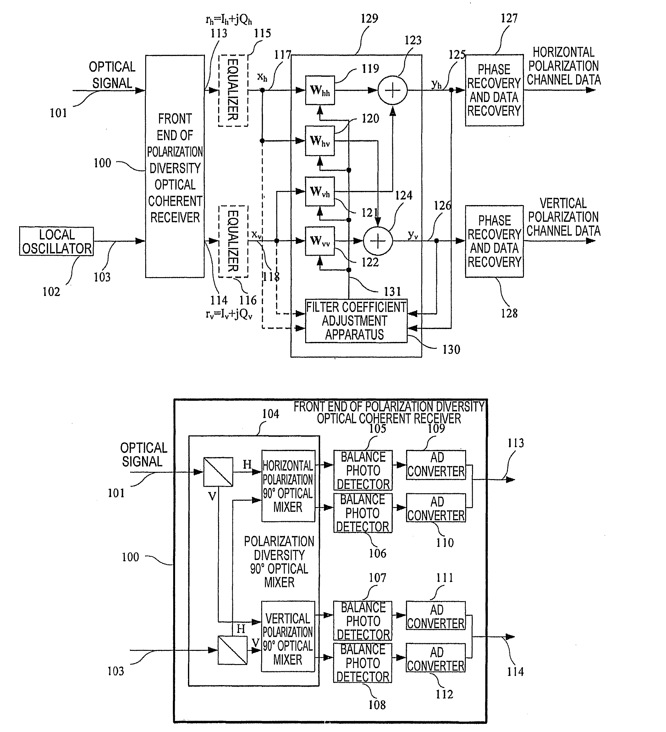
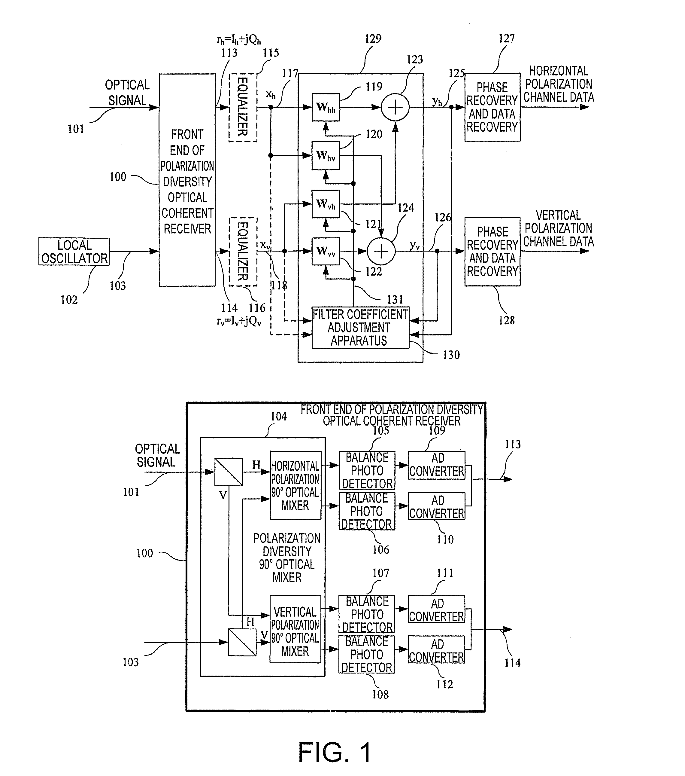
[0054]FIG. 1 shows a polarization diversity optical coherent receiver that can adopt the filter coefficient adjustment apparatus and method according to the present invention.

[0055]As shown in FIG. 1, four digital filters 119หœ122 (usually finite impulse response (FIR) filters), a filter coefficient adjustment apparatus 130, and two adders 123, 124 constitute a polarization demultiplexing apparatus 129. The input signal of the polarization demultiplexing apparatus 129 may come from output signals 113, 114 of a front end 100 of the polarization diversity optical coherent receiver, or being a signal 117 obtained by equalizing the output signal 113 with an equalizer 115 and a signal 118 obtained by equalizing the output signal 114 with an equalizer 116. The purpose of the equalizers 115, 116 is to primarily compensate transmission loss such as chromatic dispersion, so a...


PUM


Abstract

In present invention, a filter coefficient adjustment apparatus is used in a polarization demultiplexer which demultiplexes the input signals by using filters to obtain demultiplexed output signals, said filter coefficient adjustment apparatus being used for adjusting the coefficients of the filters, wherein said filter coefficient adjustment apparatus comprises: an logarithm partial derivative calculation unit for calculating the logarithm partial derivative value of a target probability density function of the demultiplexed output signals when its self-variable value is the present demultiplexed output signal value; a gradient calculation unit for calculating the gradient of a target optimizing function for optimizing the distribution of the multiplexed output signals based on the logarithm partial derivative value calculated by the logarithm partial derivative calculation unit; and a filter coefficient updating unit for updating the coefficients of the filters based on the gradient calculated by the gradient calculation unit.

Description

TECHNICAL FIELD[0001]The present invention relates to a digital coherent optical receiver. The present invention relates to a filter coefficient adjustment apparatus and method.BACKGROUND ART[0002]The polarization demultiplexing technique may double the spectrum utilization rate or capacity of an optical communication system, by optically modulating different information for two channels of carriers under orthogonal polarization state in space. On the other hand, the coherent detection technique can transit amplitudes and phase information of two optical signals in the orthogonal polarization direction to the baseband, so that all polarization information can be reserved, which makes it possible to perform polarization demultiplexing by using the signal processing technique in the digital baseband field.[0003]Different from a mobile communication, an optical network shall provide a continuous and transparent transmission function ฦ’or the upper service, and this requires the signal p...

Claims


Application Information

Patent Timeline
07 Jan 2010
Publication
US20100003028A1
IPC
H04J14/06; H04B10/00; H04B10/516; H04B10/61
CPC
H04B10/61; H04B10/611; H04J14/06; H04B10/6166; H04B10/614; H04B10/65
Inventors
ZHANG, HUIJIAN; TAO, ZHENNING