Display including a plurality of display panels

a display panel and display panel technology, applied in the field of display, can solve the problems of limited miniaturization of difficult to further miniaturize the liquid crystal display, and the difficult miniaturization of the portable telephone b>400/b>

Active Publication Date: 2008-06-17
SANYO ELECTRIC CO LTD
View PDF23 Cites 47 Cited by
  • Summary
  • Abstract
  • Description
  • Claims
  • Application Information

AI Technical Summary

Benefits of technology

[0010]The present invention provides a display allowing further miniaturization when including a plurality of display panels.

Problems solved by technology

Therefore, the portable telephone 400 is hard to miniaturize.
In the aforementioned technique of sharing the backlight, however, the main panel and the sub panel themselves are mounted independently of each other, and hence miniaturization of the liquid crystal display is limited.
Consequently, it is difficult to further miniaturize the liquid crystal display according to the aforementioned technique of sharing the backlight.
In the aforementioned technique of sharing the backlight, further, the main panel and the sub panel themselves are mounted independently of each other, and hence it is difficult to further reduce the number of components and further simplify assembling steps.
Consequently, it is also difficult to further reduce the component cost as well as the device cost.

Method used


Image

  • Display including a plurality of display panels
  • Display including a plurality of display panels
  • Display including a plurality of display panels

Examples


first embodiment

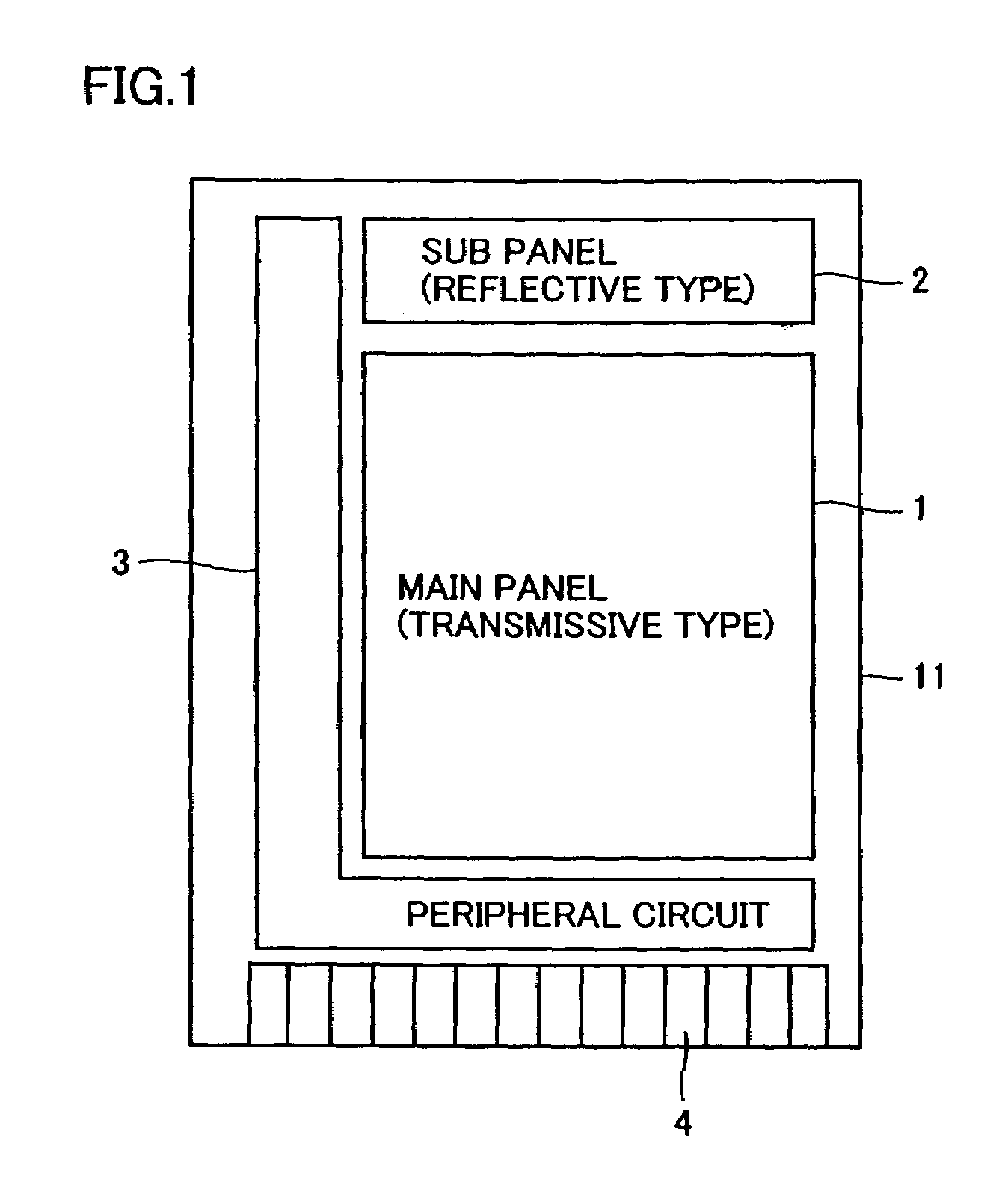
[0044]A liquid crystal display according to a first embodiment of the present invention is described with reference to FIGS. 1 and 2. According to the first embodiment, a main panel 1 and a sub panel 2 are formed on different regions of a first glass substrate 11. A peripheral circuit 3 is arranged around the main panel 1 and the sub panel 2. An external connection terminal 4 is provided on an end of the first glass substrate 11.

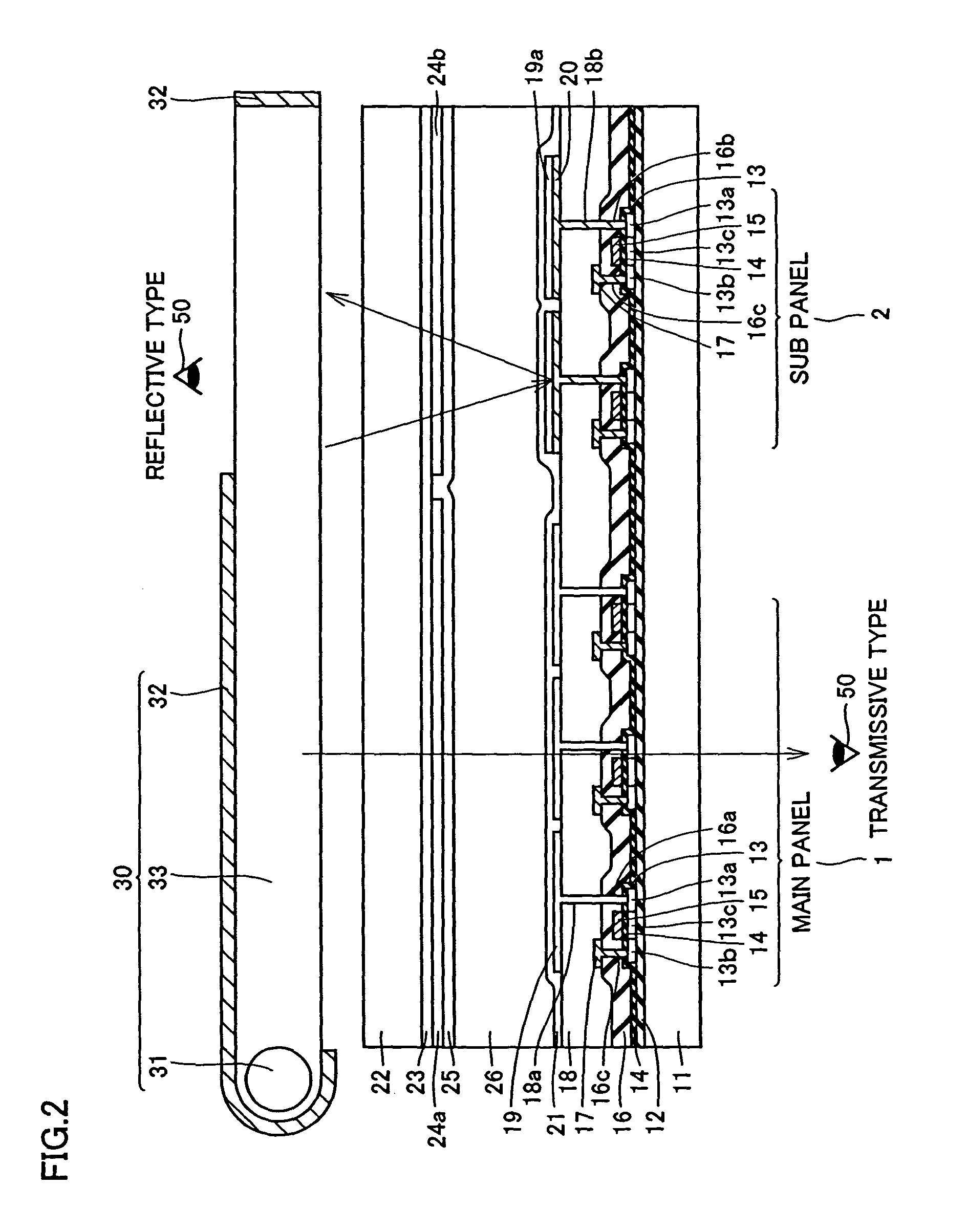
[0045]In the liquid crystal display according to the first embodiment, the main panel 1 is a transmissive panel whose display is observed by an observer 50 from the side of the first glass substrate 11 and the sub panel 2 is a reflective panel whose display is observed by the observer 50 from the side of a second glass substrate 22, as shown in FIG. 2. The first glass substrate 11 is an example of the “substrate” or the “first substrate” in the present invention, and the second glass substrate 22 is an example of the “second substrate” in the present inventi...

second embodiment

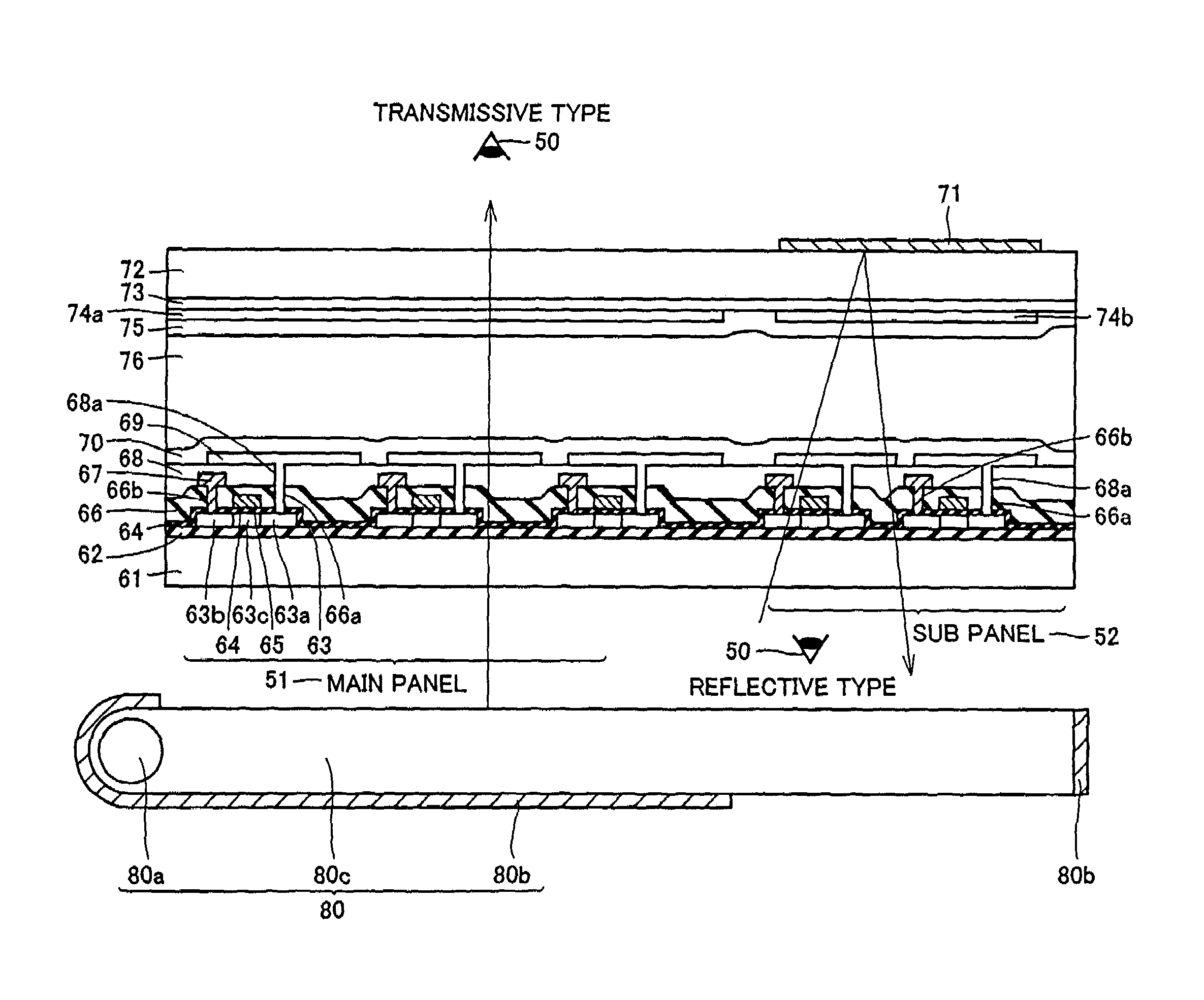
[0060]According to a second embodiment of the present invention, a main panel is observed from a side of one substrate formed with TFTs while a reflection sub panel is observed from a side of other substrate in a liquid crystal display, dissimilarly to the aforementioned first embodiments. Portions of the second embodiment different from the aforementioned first embodiment are now described in detail with reference to FIG. 4.

[0061]In the liquid crystal display according to the second embodiment, the main panel 51 and the sub panel 52 are formed on the same first glass substrate 61 as the first embodiment. The main panel 51 is a transmissive panel whose display is observed by an observer 50 from the side of the second glass substrate 72, and the sub panel 52 is a reflective panel whose display is observed by the observer 50 from the side of the first glass substrate 61. The first glass substrate 61 is an example of the “substrate” or the “first substrate” in the present invention, an...

third embodiment

[0069]According to a third embodiment of the present invention, a main panel is formed by a transflective panel and a sub panel is formed by a reflective panel in a liquid crystal display, dissimilarly to the aforementioned first and second embodiments. Portions of the third embodiment different from the aforementioned embodiments are now described in detail with reference to FIG. 5.

[0070]In the liquid crystal display according to the third embodiment, the main panel 81 and the sub panel 82 are formed on the same first glass substrate 91. The main panel 81 is a transflective panel whose display is observed by an observer 50 from the side of a second glass substrate 102, and the sub panel 82 is a reflective panel whose display is observed by the observer 50 from the side of the first glass substrate 91. The first glass substrate 91 is an example of the “substrate” or the “first substrate” in the present invention, and the second glass substrate 102 is an example of the “second substr...


PUM

PropertyMeasurementUnit
thicknessaaaaaaaaaa
frequencyaaaaaaaaaa
frequencyaaaaaaaaaa

Abstract

A display allowing further miniaturization when including a plurality of display panels is obtained. This display comprises a first display panel formed on a substrate and a second display panel formed on the same substrate on a region different from that formed with the first display panel. Thus, the display can be further miniaturized as compared with that having a first display panel and a second display panel formed on different substrates.

Description

BACKGROUND OF THE INVENTION[0001]1. Field of the Invention[0002]The present invention relates to a display, and more particularly, it relates to a display including a plurality of display panels.[0003]2. Description of the Related Art[0004]A portable display employed as the display panel of a portable telephone or the like is known in general. A folding portable telephone or the like including two display panels, i.e., a main panel and a sub panel, is also known in general.[0005]FIGS. 23 and 24 are perspective views showing the folding portable telephone 400 including two liquid crystal display panels, i.e., a main panel 401 and a sub panel 402. Referring to FIGS. 23 and 24, the conventional folding portable telephone 400 is constituted of a display part 400a and an operation part 400b. The display part 400a includes the main panel 401 provided on the surface closer to the operation part 400b and the sub panel 402 provided on the surface opposite to the operation part 400b. When the...

Claims


Application Information

Patent Timeline
Patent Type & Authority Patents(United States)
IPC IPC(8): G06F15/00G06F13/00G02F1/1333G02F1/1335G02F1/13357G02F1/1345G02F1/1368G06F3/14G09F9/35G09G3/36H04M1/02
CPCG02F1/1333G06F3/1423G09F9/35G09G3/3666H04M1/0245G02F1/1335H04M2250/16G02F1/133555G02F1/1345G02F1/1368G02F2001/133342G02F2001/133616G09G3/3677G09G3/3688G09G2300/0809G09G2300/0857G09G2310/0289H04M1/0214G02F1/133342G02F1/133616G09G3/36
Inventor SENDA, MICHIRUKOGA, MASAYUKIOKUYAMA, MASAHIROYOKOYAMA, RYOICHIAKIMA, ISAO
Owner SANYO ELECTRIC CO LTD
Why Eureka
Try Eureka