
Electromagnetic forming device for sheet of material

Active Publication Date: 2008-06-24
METAL INDS RES & DEV CENT
View PDF12 Cites 20 Cited by
  • Summary
  • Abstract
  • Description
  • Claims
  • Application Information

AI Technical Summary

Benefits of technology

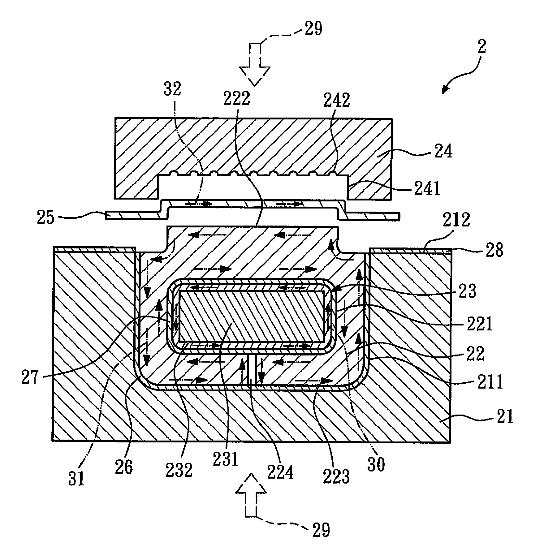
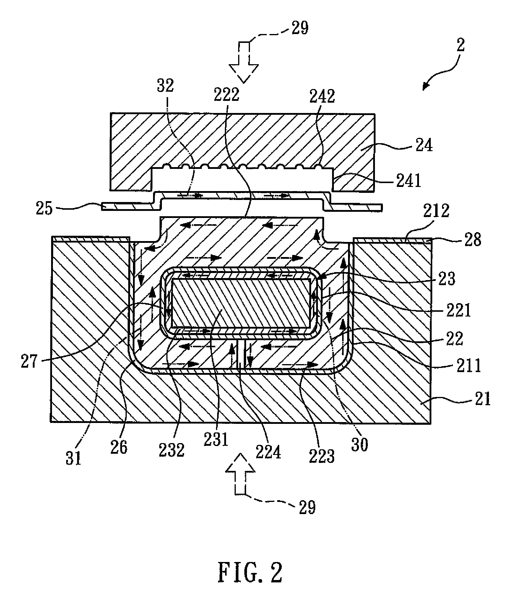
[0008]The present invention is directed to an electromagnetic forming device for a sheet of material. The electromagnetic forming device includes a fixing base, a magnetic concentration block, an electromagnetic actuator, and a die. The fixing base has a groove. The magnetic concentration block is disposed in the groove of the fixing base, and has an accommodating space therein, which is in communication with a surface of the magnetic concentration block via a slit. The electromagnetic actuator, used to generate a magnetic field, is disposed in the accommodating space of the magnetic concentration block, but does not contact the magnetic concentration block. The die and the magnetic concentration block are separated by a gap, and a sheet of material is disposed in the gap. As the magnetic concentration block is a block, eddy currents in the magnetic concentration block are distributed uniformly, so the magnetic field generated is also distributed uniformly, thus exerting a uniform forming force on the sheet of material. Moreover, in order to process products with different shapes or patterns, only the magnetic concentration block, rather than the electromagnetic actuator, needs to be replaced, so the manufacturing cost can be reduced.

Problems solved by technology

In addition, in order to process products with different shapes or patterns, different forms of electromagnetic actuator 12 must be used, so the processing cost will increase.

Method used


Image

  • Electromagnetic forming device for sheet of material
  • Electromagnetic forming device for sheet of material
  • Electromagnetic forming device for sheet of material

Examples


Embodiment Construction

[0013]FIG. 2 shows a schematic cross-sectional view of an electromagnetic forming device for a sheet of material according to a first embodiment of the present invention. The electromagnetic forming device 2 includes a fixing base 21, a magnetic concentration block 22, an electromagnetic actuator 23, and a die 24. The fixing base 21 includes a groove 211 and a first surface 212. The groove 211 is open on the first surface 212. The magnetic concentration block 22 is disposed in the groove 211 of the fixing base 21, and has an accommodating space 221, a first surface 222, a second surface 223, and a slit 224. The accommodating space 221 is disposed inside the magnetic concentration block 22, and it is in communication with the second surface 223 of the magnetic concentration block 22 via the slit 224. Alternatively, the accommodating space 221 may be in communication with the first surface 222 of the magnetic concentration block 22 via the slit 224. The first surface 222 of the magnet...


PUM

PropertyMeasurementUnit
Concentrationaaaaaaaaaa
Magnetic fieldaaaaaaaaaa

Abstract

An electromagnetic forming device for a sheet of material is provided. The electromagnetic forming device includes a fixing base, a magnetic concentration block, an electromagnetic actuator, and a die. The fixing base has a groove. The magnetic concentration block is disposed in the groove of the fixing base, and has an accommodating space therein, which is in communication with a surface of the magnetic concentration block via a slit. The electromagnetic actuator, used to generate a magnetic field, is disposed in the accommodating space of the magnetic concentration block, but does not contact the magnetic concentration block. The die and the magnetic concentration block are separated by a gap, and a sheet of material can be disposed in the gap. As the magnetic concentration block is a block, eddy currents in the magnetic concentration block are distributed uniformly, so the generated magnetic field is also distributed uniformly, thus exerting a uniform forming force on the sheet of material.

Description

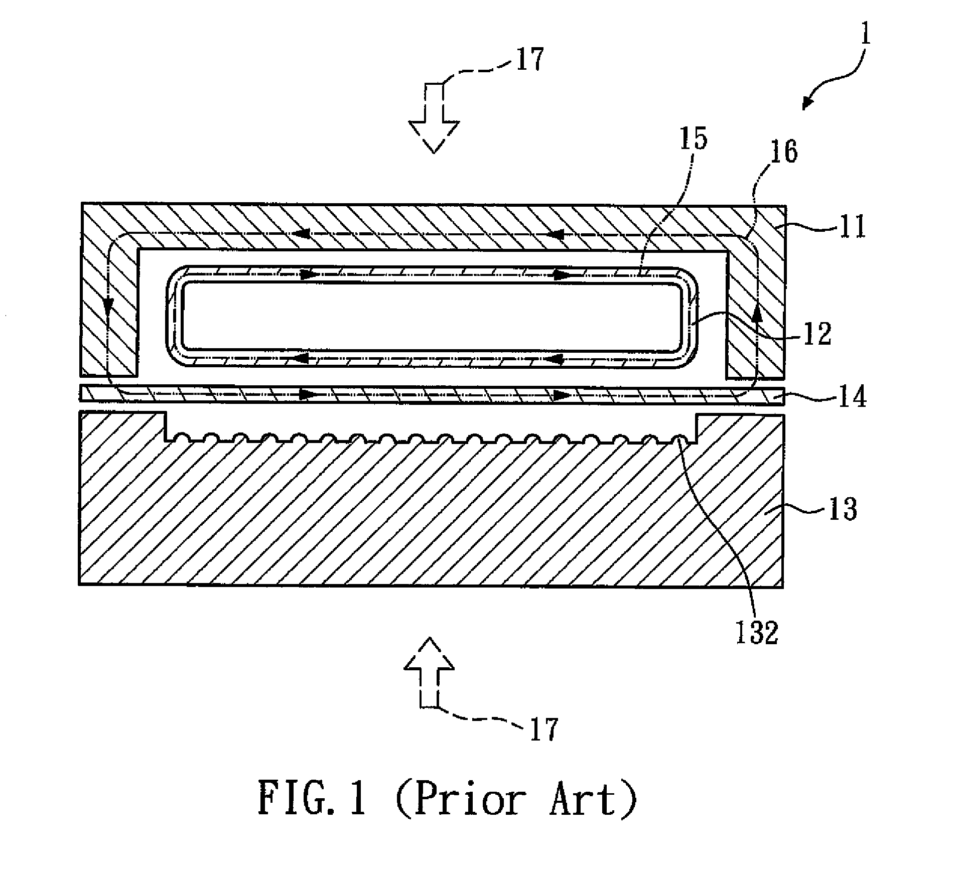
BACKGROUND OF THE INVENTION[0001]1. Field of the Invention[0002]The present invention relates to an electromagnetic forming device for a sheet of material. More particularly, the present invention relates to an electromagnetic forming device for a sheet of material including a magnetic concentration block.[0003]2. Description of the Related Art[0004]FIG. 1 shows a schematic cross-sectional view of a conventional electromagnetic forming device for a sheet of material as disclosed in U.S. Pat. No. 7,069,756. The conventional electromagnetic forming device 1 includes a conductive frame 11, an electromagnetic actuator 12, and a die portion 13. The die portion 13 defines a profiled die surface 132. The electromagnetic actuator 12 is arranged opposite the profiled die surface 132 of the die portion 13, and comprises a plurality of turns of inductive coils (not shown). A sheet of material 14 is secured in a position between the electromagnetic actuator 12 and the profiled die surface 132.[...

Claims


Application Information

Patent Timeline
IPC IPC(8): B21D26/02
CPCB21D26/14Y10S72/707
Inventor CHENG, TUNG-CHENSUE, TZYY-KERCHUNG, CHI-KEUNGWANG, CHUN-CHIEHHSIEH, HSING-TALI, MING-FU
Owner METAL INDS RES & DEV CENT
Learn More