Dip tube valve assembly

a technology a body is applied in the field of a tube valve assembly, which can solve the problems of deterioration of the quality of any subsequent material, the inability to meet the requirements of the application, so as to achieve the effect of convenient washing and resterilization in pla

Inactive Publication Date: 2008-06-24
NL TECH
View PDF40 Cites 27 Cited by
  • Summary
  • Abstract
  • Description
  • Claims
  • Application Information

AI Technical Summary

Benefits of technology

[0017]Accordingly, it is an object of the present invention to provide a device which allows for the feeding or inoculating of a material into a process, and which can be easily washed and resterilized in place.

Problems solved by technology

There are examples of devices in the prior art that provide a means to deliver or withdraw materials from a process while maintaining the integrity of the process, the sample or the feed material or the surrounding environment but these devices are restricted in their effectiveness, particularly in their abilities to maintain the integrity or character of either the sampled material or material being added to the process because these devices have designs that are optimized for use in certain physical orientations.
When used in orientations other than those they are designed for, these devices frequently suffer from the presence of crevices, particularly between component joints exposed to the process, and from design features that inhibit free flow and drainage of flowable materials through the device, resulting in pooling within the device.
Both the crevices and pooling phenomena result in material carryover from one sampling, feeding or inoculation episode to the next, causing the deterioration in quality of any subsequent material introduced through sampling, feeding or inoculating into these devices.
It is also the case that some of these devices are not designed to be reused or, if they are designed for reuse, must be removed from the process and cleaned and sometimes resterilized before being able to be used again with the process.
In the existing art, there are examples of devices that provide a means for adding materials to the process but do not provide a means for washing and resterilizing in place and for effectively draining sampled material or cleansing, rinsing or sterilizing solutions from within the device.
Today, the average cost of valves is decreasing, while the average cost of failed batches of process is increasing.
Without the availability of such a device, there is also no device available that allows, nor has a device or system been made available that would permit periodic recleaning and resterilizing of such a deadspace 311 within the production environment periodically during production runs.
As a consequence, any type of supply port 313 into a vessel or conduit 301, including gas sparging devices, may experience stagnation, material build-up and line blockages, particularly during extended production runs.
Since blockages become more severe with time, the inability to intermitently reclean and / or resterilized to remove blockages and restore full flow capacity can significantly diminish the operator's ability to control and optimize the process.

Method used


Image

  • Dip tube valve assembly
  • Dip tube valve assembly
  • Dip tube valve assembly

Examples


first embodiment

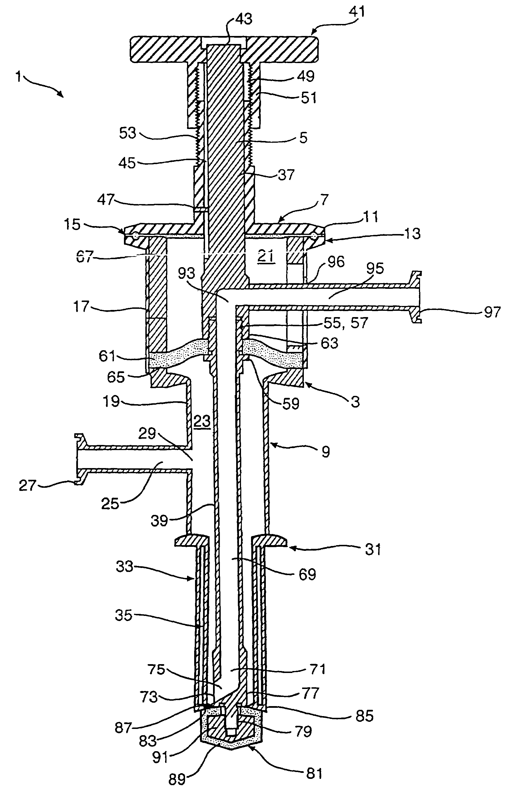
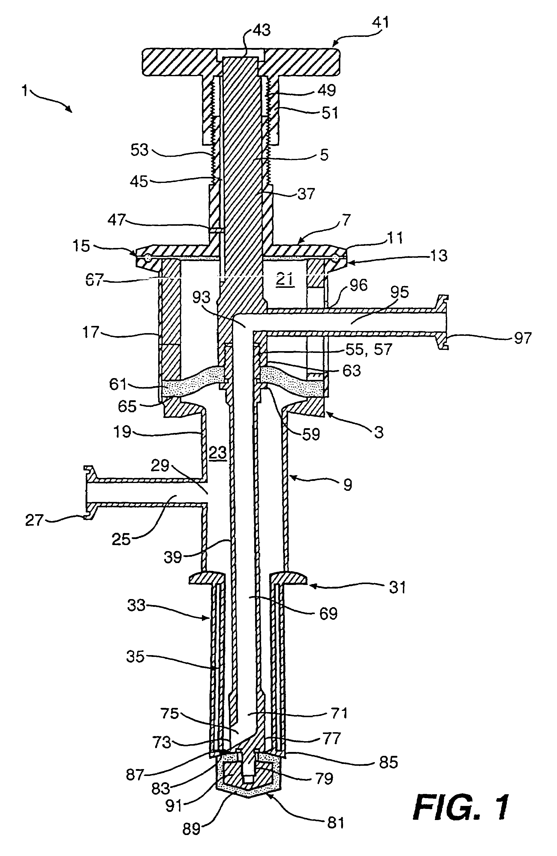
[0075]In the first embodiment, the body 3 includes a housing top 7 and a housing base 9 connected to each other through mutually engageable flanges 11 and 13 formed on the housing top 7 and housing base 9, respectively. The flanges are preferably secured together by a clamp (not illustrated); however, any other fastening means can be used, such as a plurality of bolts extending through holes formed in the perimeter of the flanges 11 and 13. A gasket 15 may be located between the flanges 11 and 13 in order to provide a sealed connection between the housing top 7 and the housing base 9.

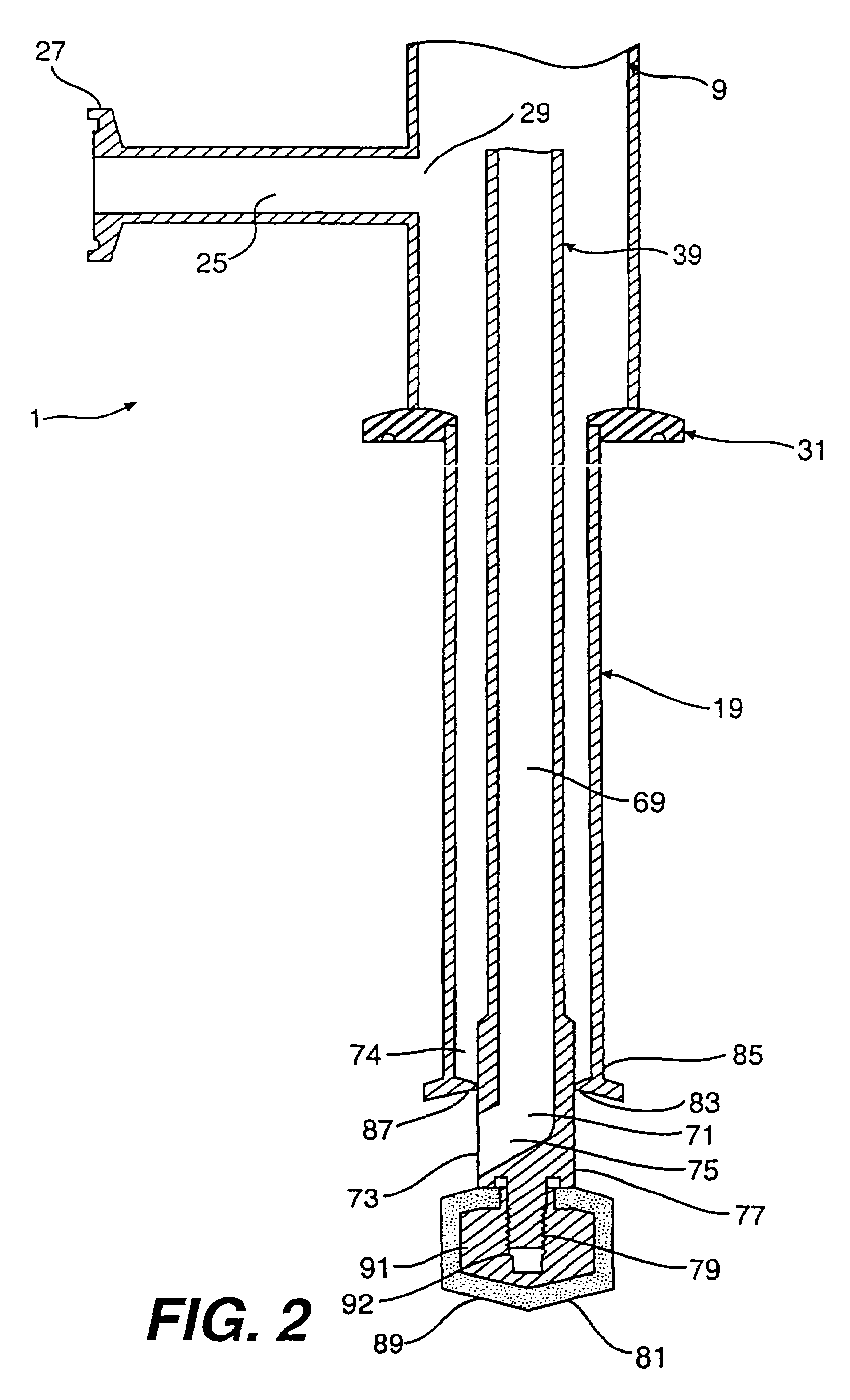
[0076]The housing base 9 includes a large diameter portion 17 and a small diameter portion 19 having cavities 21 and 23, respectively formed therein. The small diameter portion 19 includes an inlet passage 25 connected thereto for introduction of the flowable material into the cavity 23. The inlet passage 25 includes a flange 27 formed thereon for connecting to a source of the flowable material. Further...

second embodiment

[0108]In the present invention, it is possible to prevent any pooling of the material therein other than immediately adjacent to the opening 173. Furthermore, since the lower horizontal section is formed generally even with the edge of the orifice 183, and actually may slope downwardly from the orifice 183, it is possible to provide for the pooling to occur in the lower horizontal section 217 itself, since the lower horizontal section 217 is lower than or even with the bottom of the collection chamber 174 in this embodiment. In the case where the lower horizontal section 217 is lower than the bottom of the collection chamber 174, the lower horizontal section 217 forms the collection well, since the lower horizontal section 217 is the lowest point within the collection chamber 174.

[0109]Referring to FIG. 3, since the sealing tip 181 is bulged upwardly at 210 due to the flexing of the flexible outer covering 189 when in the sealed position, any material remaining in the collection cha...

third embodiment

[0128]Referring to FIGS. 8A and 8B, a description of the operation of the present invention will be described. In FIG. 8A, the sealing tip 181 is illustrated in the closed position and the flow control valves 232 and 233 are in the open position. With this orientation, it is possible to supply gas or liquid through the inlet passage 125, into the collection chamber 174 and out of the drain passage 169 as indicated by the arrows in the figure. Due to the reduced size of the collection chamber 174, the efficiency of scouring and flushing of the collection chamber 174 is improved substantially when compared with previous embodiments of the present invention.

[0129]FIG. 8A illustrates the dip tube valve assembly in the closed condition with material flowing from the supply side down to the sealing tip 181 and back up and out the drain side. However, it should be noted that the flow direction could also be reversed. In fact, during some cleaning cycles, the supply and the drain sides migh...


PUM

PropertyMeasurementUnit
physicalaaaaaaaaaa
chemical analysisaaaaaaaaaa
anglesaaaaaaaaaa

Abstract

An apparatus for sampling or feeding a flowable material through a wall of a vessel or conduit includes a body having a collection chamber formed therein. A passage has an opening operatively connected to the collection chamber. An orifice is formed in the body and is in communication with the collection chamber. The orifice is located generally adjacent the opening of the passage. A sealing device is mounted to the body to seal and unseal said orifice. Furthermore, at least a portion of the opening of the passage is located flush with or on a process side of the wall of the vessel or conduit when the apparatus is mounted to the wall of the vessel or conduit.

Description

CROSS-REFERENCE TO RELATED APPLICATIONS[0001]This application is a Continuation-In-Part of U.S. application Ser. No. 10 / 056,482 filed on Jan. 28, 2002, now U.S. Pat. No. 6,532,981, which is a Continuation of U.S. application Ser. No. 09 / 471,252 filed on Dec. 23, 1999, now U.S. Pat. No. 6,345,640. This application also claims priority under 35 U.S.C. § 119 on U.S. Provisional Application No. 60 / 113,936 filed on Dec. 24, 1998. The entirety of each of the above documents is hereby incorporated by reference.BACKGROUND OF THE INVENTION[0002]1. Field of the Invention[0003]The present invention relates to the field of sampling, feeding or inoculating of material from or to a vessel or conduit.[0004]2. Description of Related Art[0005]Quality products require precise control of many phases of a production process. It is also true that it is necessary to maintain the integrity of the process and to protect the surroundings from the process. While many advances have been made in the developmen...

Claims


Application Information

Patent Timeline
Patent Type & Authority Patents(United States)
IPC IPC(8): F16K1/44F16K37/00C12M1/26F16K41/10G01N1/20
CPCF16K41/103G01N1/2035C12M33/04G01N2001/2057Y10T137/4259Y10T137/8158Y10T137/85954
Inventor NEWBERG, DOUGLAS A.
Owner NL TECH
Why Eureka
Try Eureka