
Electrical connector with high impact strength locking assemblies

a technology of locking assembly and electric connector, which is applied in the direction of coupling device details, coatings, coupling device connections, etc., can solve the problems of bending out of shape or crease, affecting the strength of the connector, and requiring a difficult step of compressing the plug body to remove the connector, etc., to achieve the effect of high impact strength

Inactive Publication Date: 2008-06-24
D S M & T
View PDF19 Cites 55 Cited by
  • Summary
  • Abstract
  • Description
  • Claims
  • Application Information

AI Technical Summary

Benefits of technology

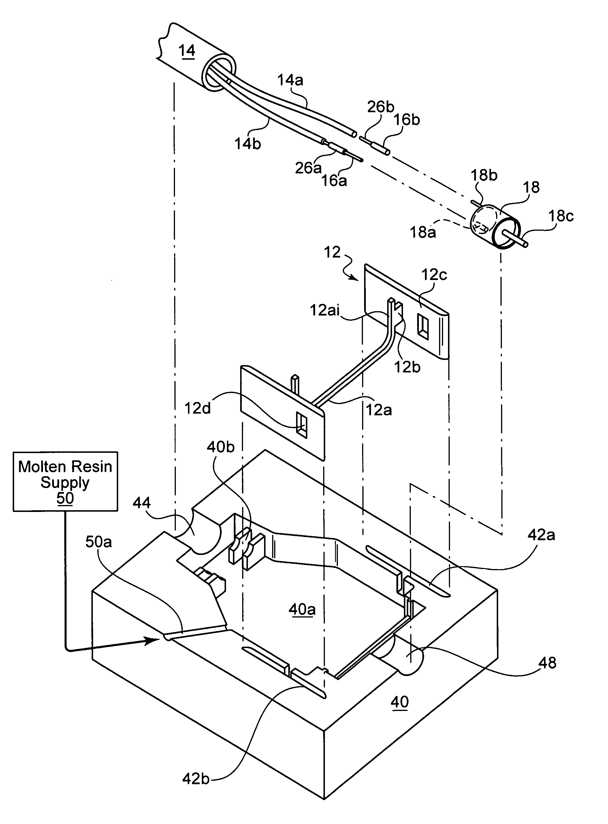
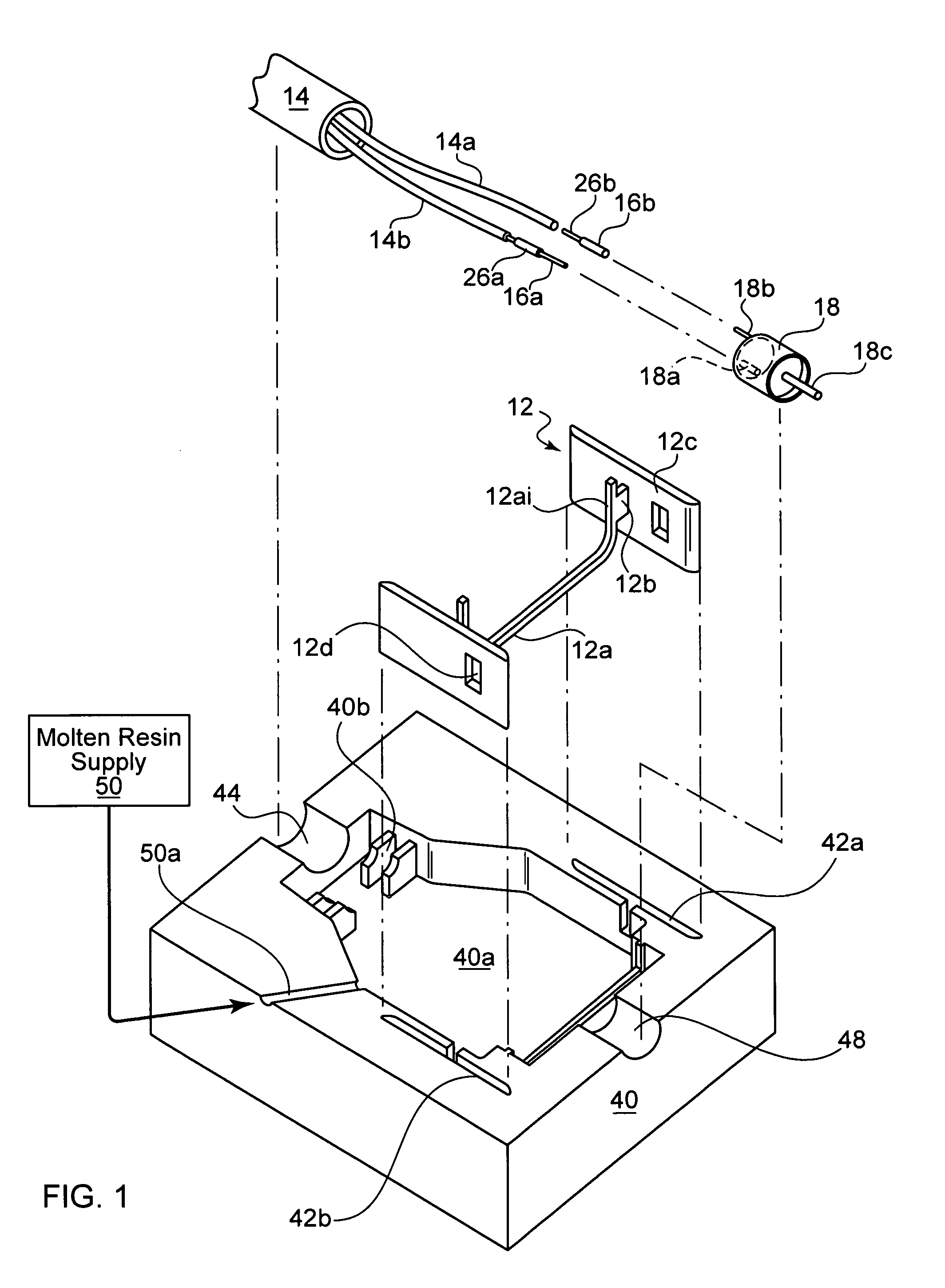
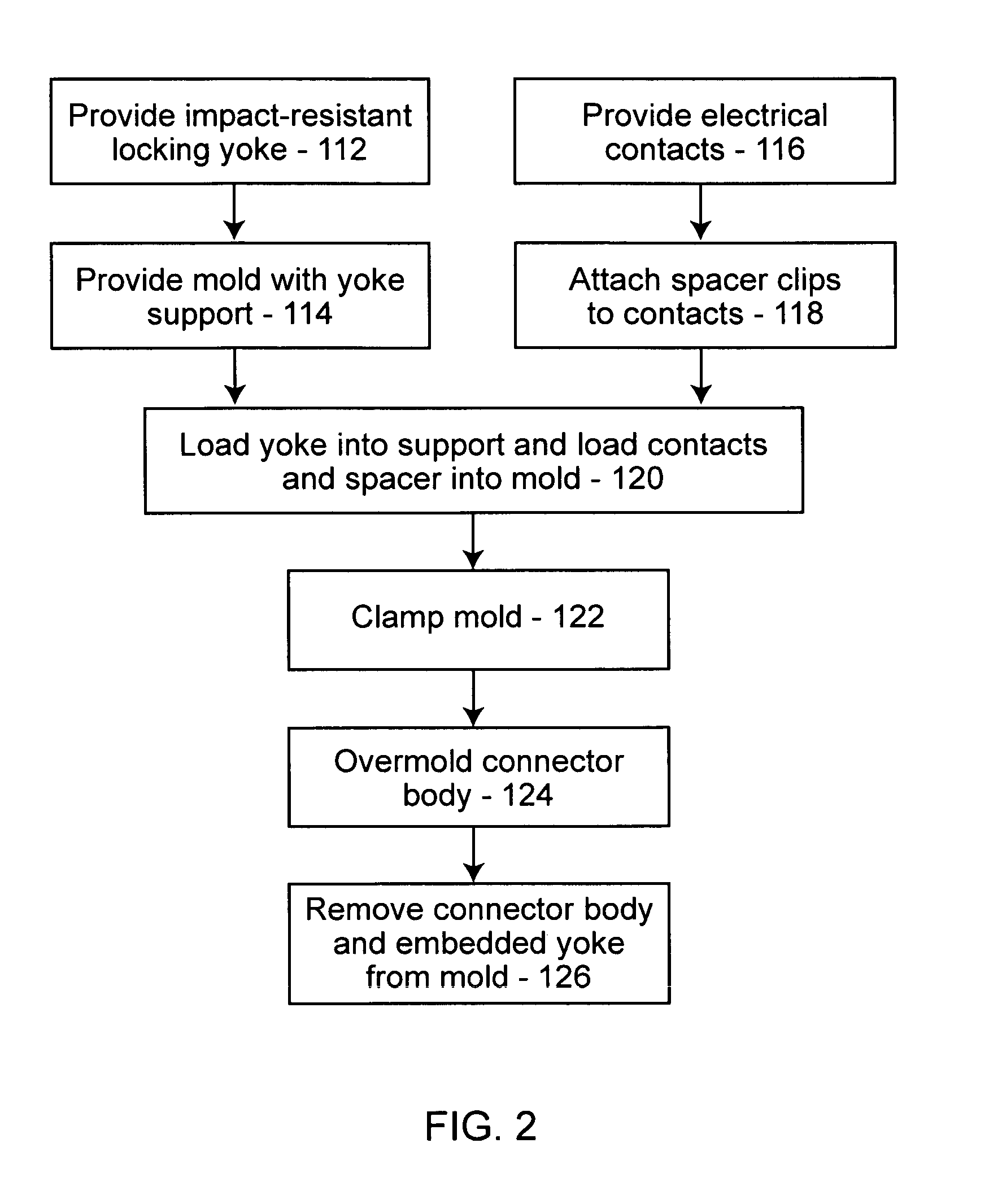
"The present invention provides a weather-proof electrical connector with high impact strength locking assemblies. The connector has a male and female connector with a mating seal formed upon connection. The male connector has locking tabs and the female connector has a locking yoke with impact resistant material. The locking yoke has pivot plates and the impact resistant material has a tensile strength at yield of between 7,500 psi to 10,500 psi. The connector also includes a retention band and the impact resistant material has a tensile strength at yield of between 3 and 20 times greater than the dielectric material. The connector has a simplified method of manufacturing with a single overmolding step. The connector can be installed onto a mounting plate with flexible arms and the attachment assembly is securely mounted with an impact resistant material. The connector also has posts for supporting the electrical contacts and a sleeve for encasing the contacts before they enter within arcing range."

Problems solved by technology

Removing these connectors requires a difficult step of compressing the plug body to allow the ramps to clear the aperture.
The removal process may place undue torque or force on the mounting plate causing it to bend out of shape or crease.

Method used


Image

  • Electrical connector with high impact strength locking assemblies
  • Electrical connector with high impact strength locking assemblies
  • Electrical connector with high impact strength locking assemblies

Examples


Embodiment Construction

[0027]The present invention incorporates locking assemblies made from selected engineering resins into an overmolded plug body for improved performance. Through careful design of the locking assemblies, a weather resistant electrical connector with improved functionality can be manufactured with a single overmolding step.

[0028]A variety of electrical connectors are known, for example, mini spa plugs and connectors for evaporative cooling applications. Our prior designs have provided mating seals to restrict moisture from penetrating the electrical contact areas. However, upgrading or maintaining the equipment frequently requires the electrical connectors to be removed or replaced. The material used to form the plug body and the receptacle body is chosen for its dielectric properties. The material's mechanical properties including excellent flex fatigue resistance make it ideal for sealing. In addition, the electrical connectors typically lock to each other and latch onto a mounting ...


PUM

PropertyMeasurementUnit
tensile strengthaaaaaaaaaa
heightaaaaaaaaaa
dielectric constantaaaaaaaaaa

Abstract

A weather-resistant electrical connector having an environmental seal and including a locking assembly made from a high impact strength thermoplastic. A method is disclosed for overmolding the connectors in one step. A locking yoke latches the connectors together. Locking tabs secure the connectors to mounting plates. The locking tabs have steps to retain the connectors upon compression of a seal. An insulated mounting post supports the contact and is of sufficient length to seal and contain any arcs from live connections.

Description

BACKGROUND OF THE INVENTION[0001]1. Field of the Invention[0002]The present invention relates to a method and apparatus involving overmolded, weather resistant electrical connectors having locking assemblies made from a different high strength and flexible material.[0003]2. The Prior Art[0004]Plug and receptacle bodies can be made from a variety of methods, including overmolding a dielectric material around the wires and contacts. Improvements in the basic design add features on to the overmolded body. One example is commonly owned U.S. Pat. No. 5,401,181, the entire content of which are incorporated herein by reference thereto. This patent is incorporated by reference to provide a description of the fluid sealing feature.[0005]In order to improve the integrity of the electrical connection, manufacturers began adding latching assemblies. One example is commonly owned U.S. Pat. No. 6,379,169 which adds overmolded latch parts to each connector. Another example is commonly owned U.S. P...

Claims


Application Information

Patent Timeline
Patent Type & Authority Patents(United States)
IPC IPC(8): H01R13/52
CPCB29C45/14065B29C45/14639H01R13/405H01R13/5219H01R43/24B29C2045/14139H01R13/6273
Inventor CORONA, SERGIO
Owner D S M & T
Learn More